Impact forming of thermoplastic composites

a technology of thermoplastic composites and impact forming, which is applied in the direction of liquid surface applicators, coatings, layered products, etc., can solve the problems of warpage of materials, adversely affecting the integrity of thermoplastic composite materials, etc., and achieves improved fuel economy, reduced weight of thermoplastic composite parts, and increased performance

Active Publication Date: 2020-08-06
TRELLEBORG SEALING SOLUTIONS GERMANY
View PDF2 Cites 2 Cited by
  • Summary
  • Abstract
  • Description
  • Claims
  • Application Information

AI Technical Summary

Benefits of technology

[0006]Disclosed embodiments overcome the aforementioned problems by using a peening system in place of, or in addition to, a compaction roller. The peening system may include a needle peening system, a shot peening system, an electronically activated peening system, a combination thereof, or another suitable peening system. With a peening system, pins or particles (in the case of shot peening) provide improved compaction coverage over the complex surfaces, improving the quality and integrity of the thermoplastic composite material.
[0007]Additional benefits of use of the peening system include improving consolidation. The multiple impacts and high dynamic loads of the peening system, provide the ability to conform to uneven surfaces results in improved laminate consolidation. Additionally, the multiple impacts, high dynamic loads, and the ability to conform to uneven surfaces results in reduced voids. In particular, the high dynamic compaction loads result in void collapse, improving structural integrity. Furthermore, similar to work hardening of metals by impact processing, impact forming of thermoplastic composites increases the crystallinity of semi-crystalline polymers. The strain hardening of semi-crystalline polymers due to increased crystallization also contributes to improved structural integrity of the thermoplastic composite material.
[0008]The use of the peening system in disclosed embodiments may further provide the benefits of relieving residual stress of the thermoplastic materials. The thermoplastic composite material typically comprises a polymer material with fibers dispersed throughout. The composite is heated, and while in a heated state, gets compacted. As the polymer cools, it contracts. Typically, the polymer has a different coefficient of thermal expansion (CTE) than the fibers. As the material cools, a residual stress builds up that can cause warpage of the material. The peening process relaxes the residual stress, serving to reduce warpage. Thus, the impacts from the peening system impart compressive stress in the thermoplastic composite material (laminate) to counteract the tensile stress that results from CTE and crystallization induced shrinkage during in-situ consolidation (ISC). The number of impacts, frequency of impacts, impact force, temperature of the laminate, and other variables can be controlled to relieve or compensate for residual stresses.

Problems solved by technology

With these complex surfaces, a compaction roller often cannot provide complete compaction coverage, resulting in voids in the thermoplastic composite material that adversely affect the integrity of the thermoplastic composite material.
In particular, the high dynamic compaction loads result in void collapse, improving structural integrity.
As the material cools, a residual stress builds up that can cause warpage of the material.

Method used


Image

  • Impact forming of thermoplastic composites
  • Impact forming of thermoplastic composites
  • Impact forming of thermoplastic composites

Examples


Embodiment Construction

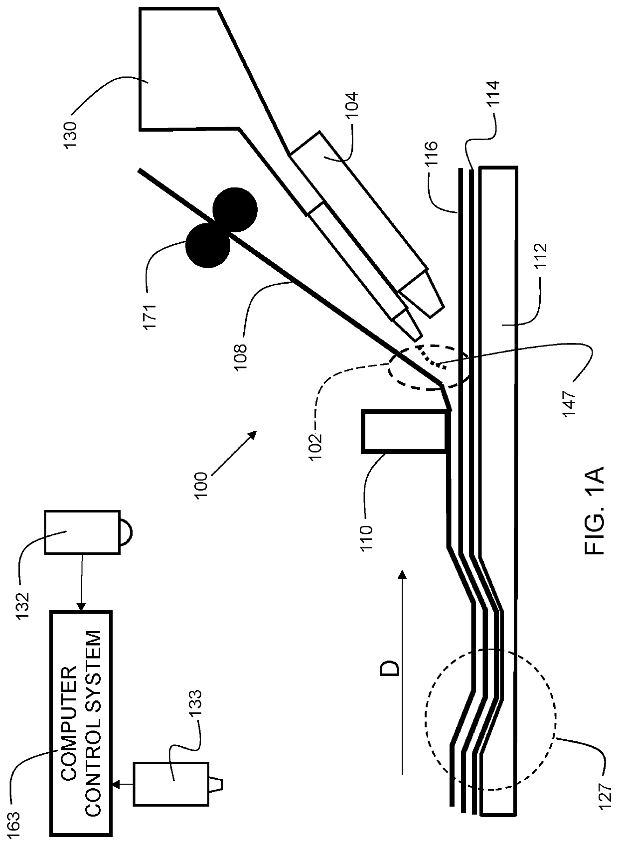
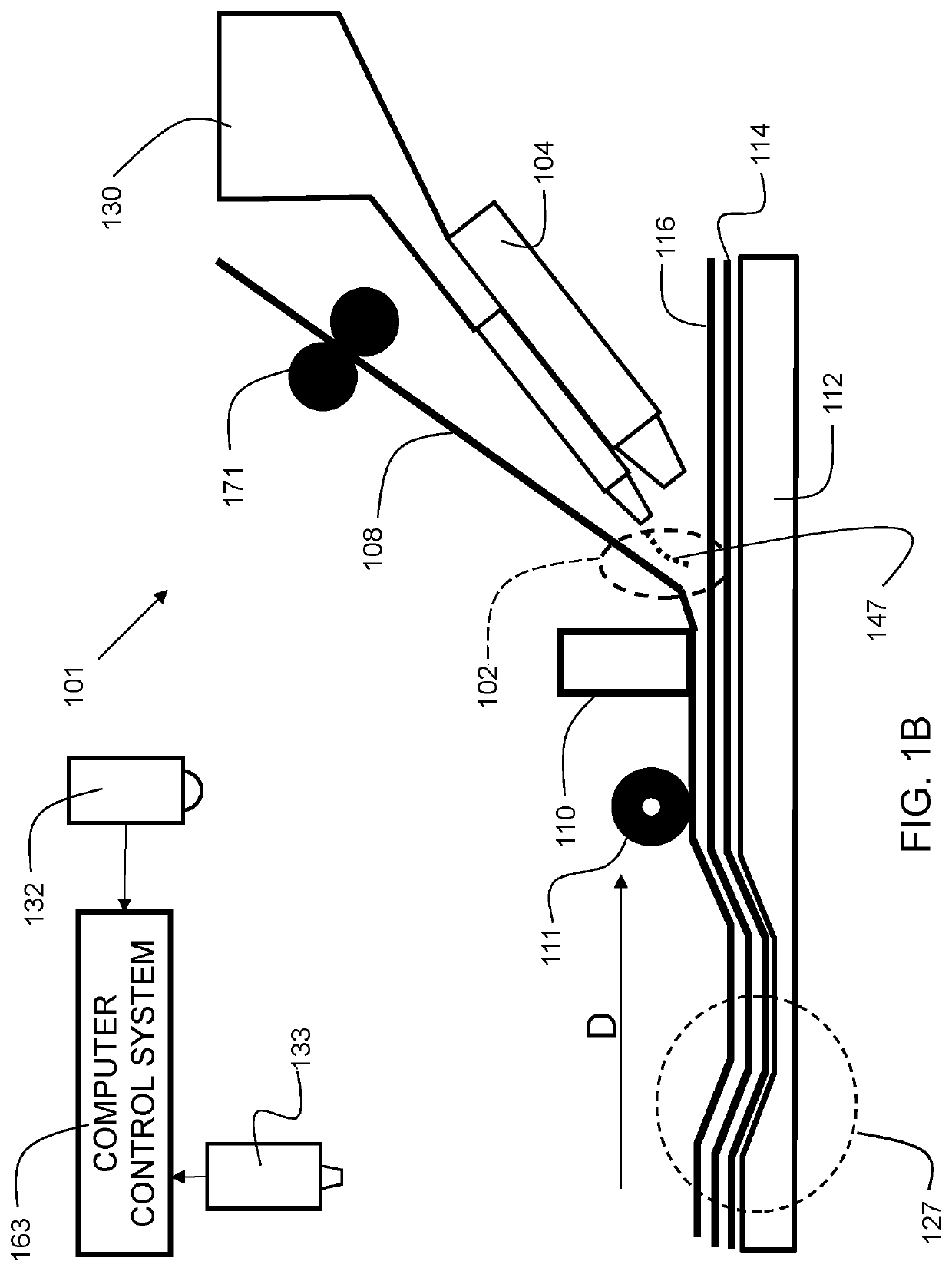
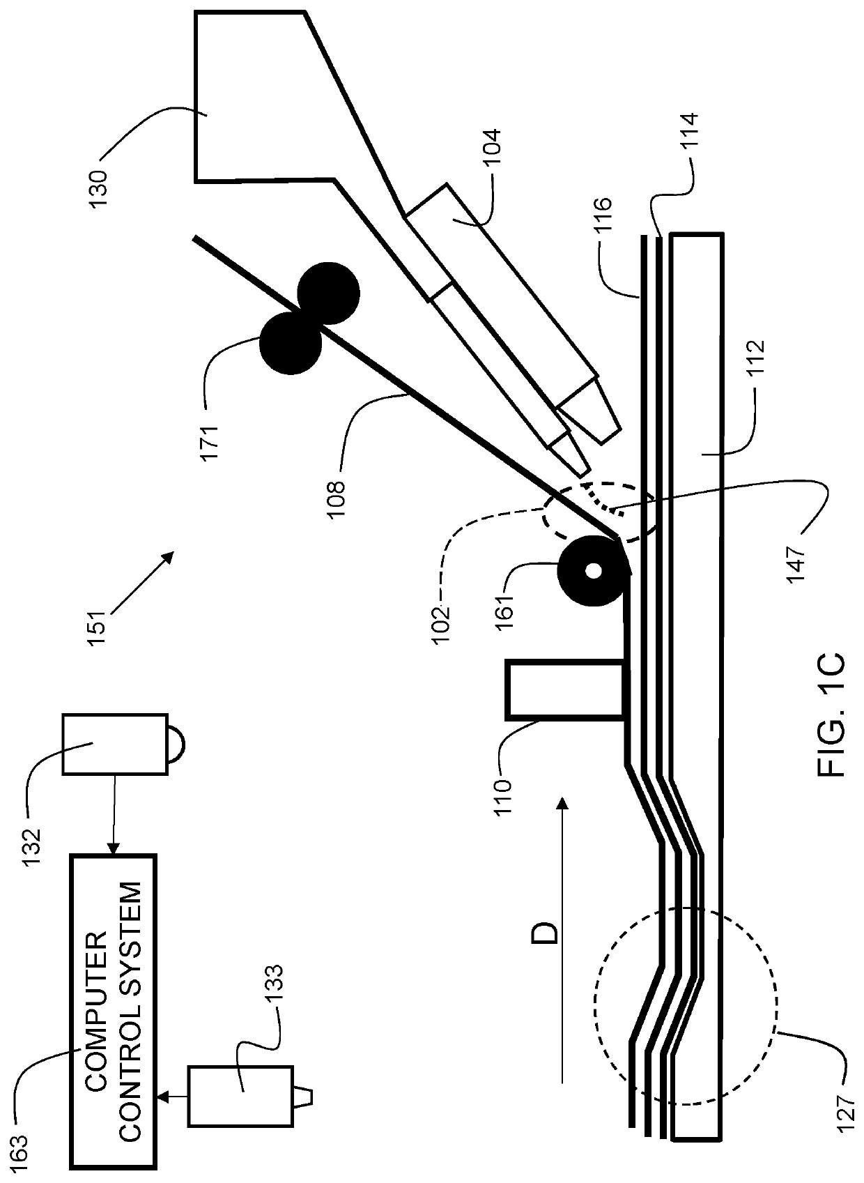
[0025]Disclosed embodiments provide automated fiber placement techniques for fabrication of parts made from composite materials. In some embodiments, tape plies are wound around a mandrel while, optionally, a polymer is dispensed on a tape ply shortly before compaction. A peening system with multiple pins provides compaction over irregular surfaces, providing superior performance as compared with traditional compaction rollers.

[0026]Reference throughout this specification to “one embodiment,”“an embodiment,”“some embodiments”, or similar language means that a particular feature, structure, or characteristic described in connection with the embodiment is included in at least one embodiment of the present invention. Thus, appearances of the phrases “in one embodiment,”“in an embodiment,”“in some embodiments”, and similar language throughout this specification may, but do not necessarily, all refer to the same embodiment.

[0027]Moreover, the described features, structures, or characteri...


PUM

PropertyMeasurementUnit
Frequencyaaaaaaaaaa
impact pressureaaaaaaaaaa
glass transition temperatureaaaaaaaaaa

Abstract

Disclosed embodiments provide automated fiber placement techniques for fabrication of parts made from composite materials. A peening system with multiple pins provides compaction over irregular surfaces, providing superior performance as compared with traditional compaction rollers. The apparatus that carries out the techniques include a tape dispensing system, a heating system, a peening system, a processor and a memory coupled to the processor. The memory contains instructions that when executed by the processor perform the steps of: dispensing a first ply of thermoplastic composite tape over a mandrel; dispensing a second ply of thermoplastic composite tape on the first ply; and peening the second ply onto the first ply, such that the second ply is bonded to the first ply.

Description

CROSS REFERENCE TO RELATED APPLICATIONS[0001]This is a non-provisional application based upon U.S. provisional patent application Ser. No. 62 / 799,864, entitled “IMPACT FORMING OF THERMOPLASTIC COMPOSITES”, filed Feb. 1, 2019, which is incorporated herein by reference.BACKGROUND OF THE INVENTION1. Field of the Invention[0002]The present invention relates generally to an apparatus that forms composite structures, and more particularly, to impact forming of thermoplastic composites.2. Description of the Related Art[0003]Thermoplastic composite structures are formed by melt bonding layers of reinforced thermoplastic polymers. In recent years, composite materials are being used for a variety of applications that previously relied on metal. High strength and lightweight, composite materials are being used in parts such as aircraft wings, automobile rims, and other critical components. While composite materials provide improved performance in terms of strength to weight ratios, the time an...

Claims


Application Information

Patent Timeline
Patent Type & Authority Applications(United States)
IPC IPC(8): B29C63/00B29C65/00B24C1/10B29C63/48
CPCB29C2063/483B29L2009/00B32B2274/00B29C66/95B05D1/02B05D2201/00B29C63/48B29C63/003B24C1/10B29C66/8341B29C70/30B29C66/41B29C66/1122B29C66/721B29C66/8362B29C65/08B29C66/81465B29C65/40B29C65/02B29C65/4815B29C65/524B29C66/91221B29C66/91216B29C66/91641B29C66/343B29C66/9672B29C66/71B29C66/919B29C66/91943B29C66/929B29C66/81423B29K2071/00B29C70/40B29C70/545B29C70/34
Inventor HAUBER, DAVID EDGAR
Owner TRELLEBORG SEALING SOLUTIONS GERMANY
Why Eureka
Try Eureka