
Laser welding method

a laser welding and welding method technology, applied in welding/soldering/cutting articles, cladding optical fibre, manufacturing tools, etc., can solve the problems of deformation and weakening of the processed workpiece, cracks, and defects at the termination of laser welding, and achieve the effect of reducing the number of defects and cracks

Active Publication Date: 2020-08-13
COHERENT INC
View PDF0 Cites 12 Cited by
  • Summary
  • Abstract
  • Description
  • Claims
  • Application Information

AI Technical Summary

Benefits of technology

The present invention provides a method for laser welding a workpiece using a focused beam of laser-radiation. The focused beam has a small center beam and a larger annular beam that is ramped down to an off-power during movement of the focus. The center beam is ramped up and down during the ramp-down time, and the annular beam is ramped up and down over two time durations. The technical effects include improved weld quality, reduced burn-through, and improved surface quality.

Problems solved by technology

Traditional mechanical processing produces unwanted defects, such as micro-cracks that may propagate when a processed workpiece is stressed, thereby degrading and weakening the processed workpiece.
However, it can be difficult to maintain a stable keyhole in a hot and dynamic pool of melted material.
One problem when laser welding some metals and metal alloys is the formation of defects, particularly cracks, at the termination of a laser weld.
Some defects are caused by stress that is induced while the workpiece is cooling.
These initial defects weaken a welded workpiece and may further propagate if thermal or mechanical stress is applied when the finished welded workpiece is used.
An unreliable weld could lead to catastrophic failure.
Although these solutions have been successful for many materials, they have proven insufficient for modern high-strength alloys or metals having relatively high thermal conductivity.
These materials remain stubbornly prone to cracking at the beginning and / or termination of a laser weld, particularly at the termination of a laser weld.

Method used


Image

  • Laser welding method
  • Laser welding method
  • Laser welding method

Examples


Embodiment Construction

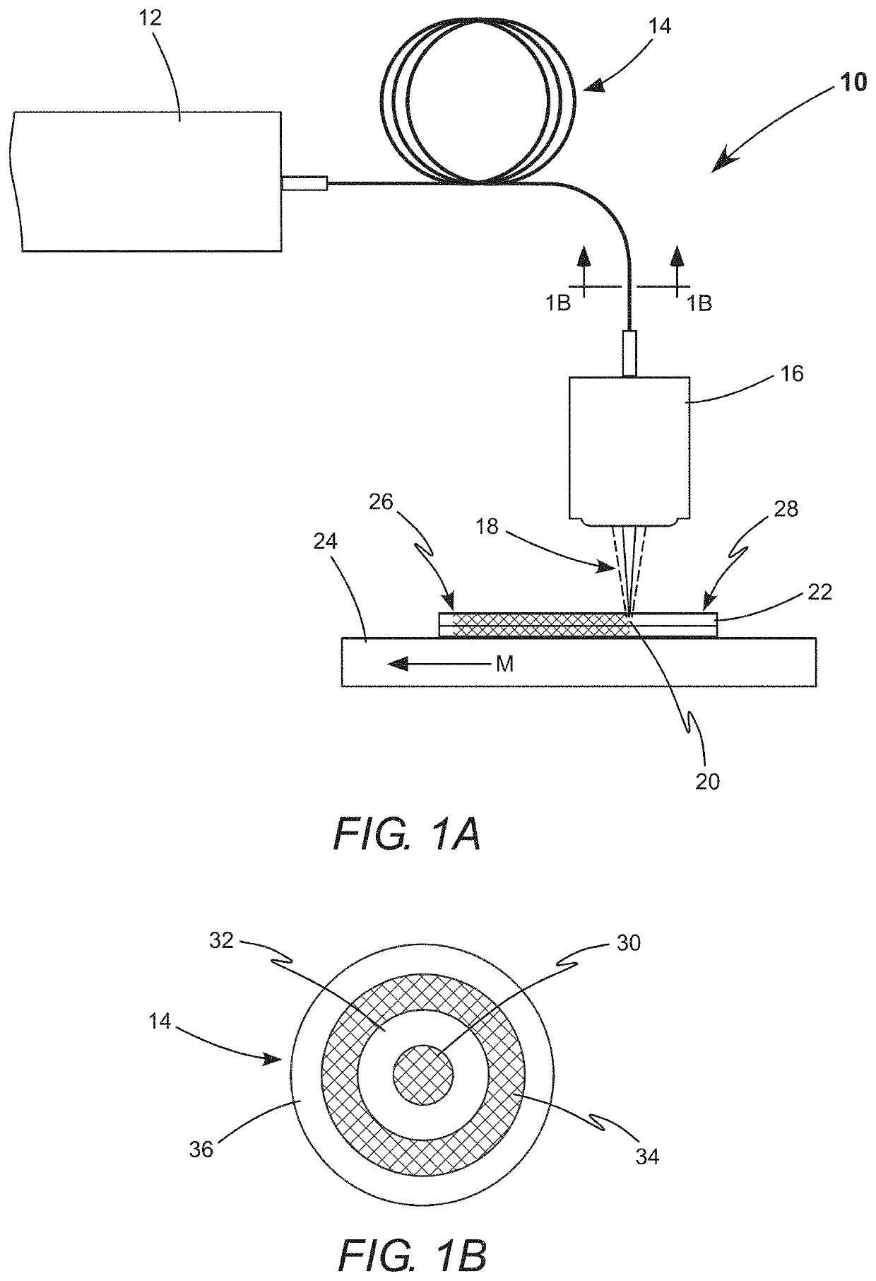
[0017]Referring now to the drawings, wherein like components are designated by like numerals, FIGS. 1A and 1B schematically illustrate an apparatus 10 used in prior-art laser processing methods and which is used in the laser welding method of the present invention. In both the prior-art and current methods, a laser source 12 delivers at least two beams of laser-radiation through an optical fiber 14 to a focusing lens 16. Optical fiber 14 includes a center core 30 for guiding a center beam of laser-radiation. Center core 30 has a low refractive index cladding 32. Optical fiber 14 further includes an annular core 34 for guiding an annular beam of laser-radiation. Annular core 34 is concentrically located between low refractive index cladding 32 and a low refractive index cladding 36. Laser source 12 is configured to deliver the center beam to center core 30 and the annular beam to the annular core 34. Laser systems integrating such a laser source with such an optical fiber are commerc...


PUM

PropertyMeasurementUnit
depthaaaaaaaaaa
depthaaaaaaaaaa
off-poweraaaaaaaaaa

Abstract

A method for laser keyhole welding of metal alloys is disclosed. The method independently adjusts power in a focused center beam and power in a concentric focused annular beam. At the termination of a weld, the power in the center beam is initially ramped up and then ramped down, while the power in the annular beam is ramped down. Increasing the power in the center beam enables a controlled and prolonged contraction of the keyhole and melt pool, thereby preventing undesirable cracking.

Description

PRIORITY[0001]This application claims priority to U.S. Provisional Application Ser. No. 62 / 805,244, filed Feb. 13, 2019, the disclosure of which is incorporated herein in its entirety.TECHNICAL FIELD OF THE INVENTION[0002]The present invention relates in general to welding using focused beams of laser-radiation. The invention relates in particular to welding metal alloys using a focused center beam and a focused annular beam.DISCUSSION OF BACKGROUND ART[0003]Beams of laser-radiation are increasingly used for cutting, drilling, welding, marking, and scribing workpieces made of a wide range of materials; including metals and metal alloys. Traditional mechanical processing produces unwanted defects, such as micro-cracks that may propagate when a processed workpiece is stressed, thereby degrading and weakening the processed workpiece. Laser processing minimizes such unwanted defects, is generally cleaner, and causes a smaller heat-affected zone. Laser machining uses a focused laser beam...

Claims


Application Information

Patent Timeline
Patent Type & Authority Applications(United States)
IPC IPC(8): B23K26/06B23K26/073B23K26/70B23K26/082B23K26/22
CPCB23K26/702B23K26/0665B23K26/0734B23K26/0626B23K26/082B23K2103/10B23K26/22B23K2103/04B23K26/0613B23K26/0608B23K26/24G02B6/02042
Inventor BRESCOE, RYANLAVOIE, JEAN-PHILIPPE
Owner COHERENT INC
Features
  • Generate Ideas
  • Intellectual Property
  • Life Sciences
  • Materials
  • Tech Scout
  • Unparalleled Data Quality
  • Higher Quality Content
  • 60% Fewer Hallucinations
Learn More