Bypass catheter

a catheter and bypass technology, applied in balloon catheters, medical science, surgery, etc., can solve the problems of affecting the flow of blood to other sites near the targeted site, affecting the flow of blood to other sites, requiring multiple operations at the same targeted site, etc., and achieve the effect of reducing the diameter

Active Publication Date: 2020-08-20
WALZMAN DANIEL EZRA
View PDF3 Cites 8 Cited by
  • Summary
  • Abstract
  • Description
  • Claims
  • Application Information

AI Technical Summary

Benefits of technology

[0025]In some embodiments, the apparatus includes a sheath positioned over the elongated member, the elongated member and sheath relatively movable to selectively cover and expose the side hole, wherein covering of the side hole restricts flow of blood through the side hole. In some embodiments, covering of the hole completely blocks flow of fluid through said side hole.
[0026]In some embodiments, the apparatus has features to restrict retrograde blood flow within said catheter such as a valve or a reduced diameter region for the first lumen. In some embodiments, attaching pressurized fluid to the catheter at a proximal region can restrict retrograde blood flow within said catheter.

Problems solved by technology

One of the problems associated with using balloons is that although control of the blood flow through a portion of the blood vessel is achieved, including blockage of the blood supply to a targeted site, blood flow is completely interrupted to other sites near the targeted site.
However, such interruption of blood flow becomes problematic when used for a longer duration.
That is, complex medical procedures may not be achieved during said short duration resulting in injury to other sites or requiring multiple operations at the same targeted site.
Additionally, current bypass catheters are designed to be surgically implanted, which is not practical for immediate relief of progressive ischemia caused by a sudden blockage of a blood vessel, such as from a thrombus or embolus.
However, these devices do not provide for adequate controlling of blood flow during the procedure.
Furthermore, these procedures can often be lengthy, and most often do not provide immediate restoration of flow to the ischemic territory.
None of the current devices achieves this.

Method used


Image

  • Bypass catheter
  • Bypass catheter
  • Bypass catheter

Examples


Embodiment Construction

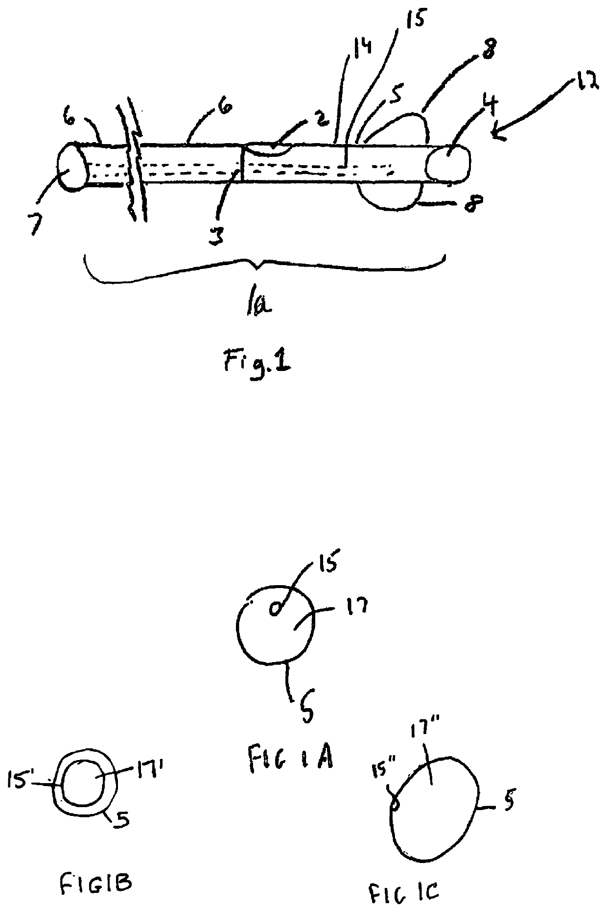
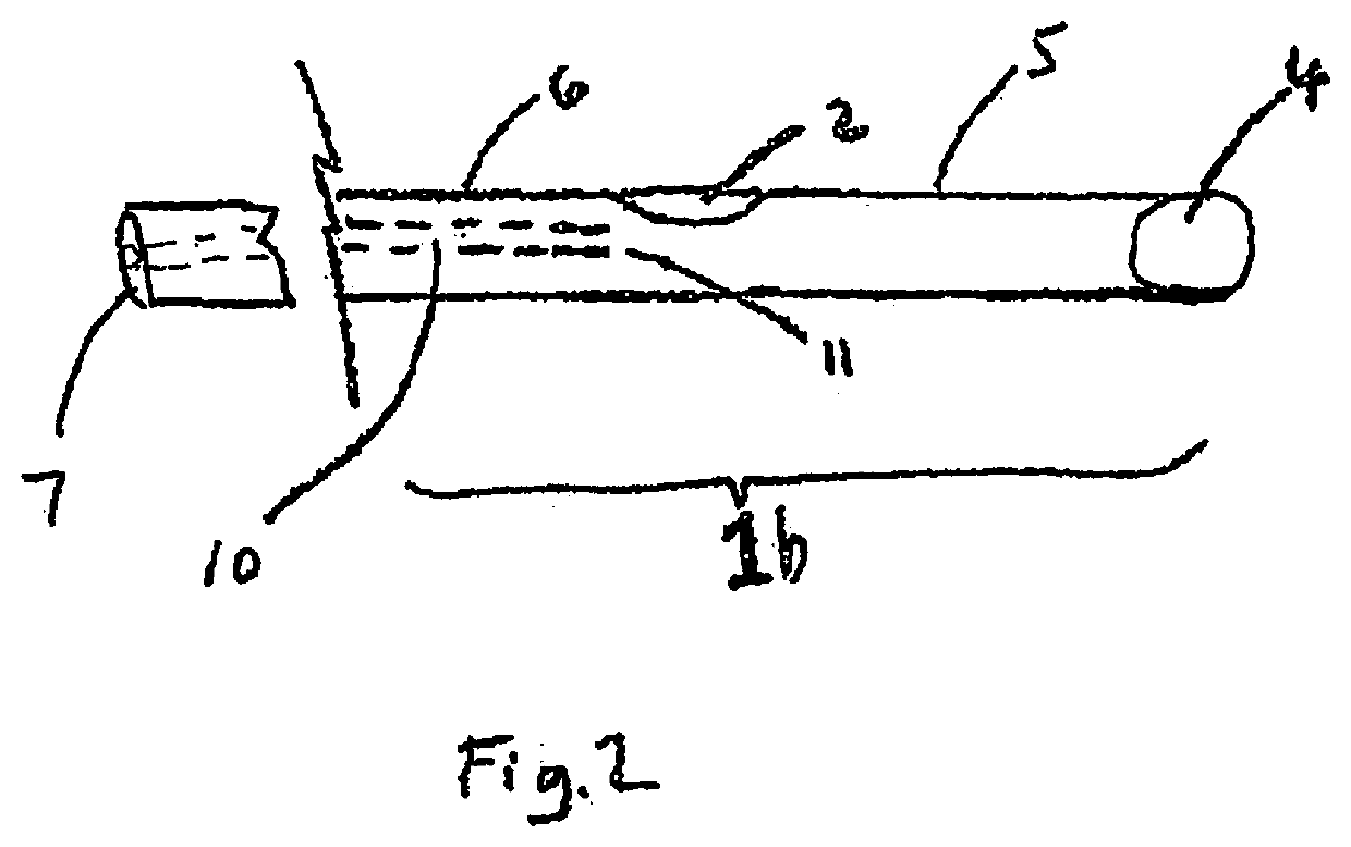
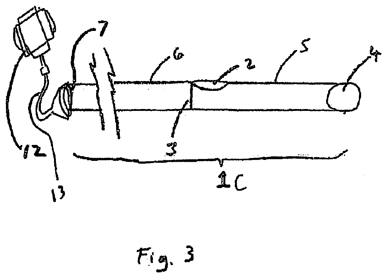
[0073]The present invention provides a catheter and method for use in the blood vessel of a patient during a blood clot treatment procedure. The catheter advantageously provides for blood flow during various clot treatment / removal procedures such as mechanical thrombectomy utilizing rotational element(s) to break up the clot, devices that deliver thrombolytics to dissolve blood clots, devices that delivery vibrational energy in the form of continuous or pulsating waves, devices that deliver energy to aid and / or effect blood clot removal, etc., as well as combinations thereof. These various embodiments are described in detail below.

[0074]The devices of the present invention provide for controlling blood flow during the procedure to thereby enable immediate and, if desired, continuous, reperfusion during the procedure. They allow rapid restoration of temporary flow of blood through a blockage to avoid ischemic injury, with immediate restoration of a degree of flow beyond a clot. This ...


PUM


Abstract

A surgical apparatus for treating a blood clot in a vessel of a patient having an elongated member having an outer wall, a first hole at a distal portion and a second hole spaced proximally from the first hole positioned in a side wall. A first lumen is provided within the elongated member for blood flow through the second hole, through the lumen and exiting the first hole to maintain blood flow during treatment of the blood clot. An energy emitter emits energy to the blood clot or hardenings and a connector connects the energy emitter to an external energy source, wherein blood flows into the second hole positioned proximal of the blood clot and exits the first hole distal of the blood clot during activation of the energy emitter. In some instances when the apparatus is introduced from a retrograde ‘upstream” approach blood may flow through the device in the opposite direction.

Description

[0001]This application is a continuation in part of application Ser. No. 15 / 932,911, filed May 18, 2018, which is a continuation in part of application Ser. No. 15 / 732,953, filed Jan. 16, 2018. The entire contents of each of these applications are incorporated herein by reference.BACKGROUND OF THE INVENTION1. Field of the Invention[0002]The present invention relates generally to a catheter placed in a minimally invasive manner, and, more particularly, to a bypass catheter to ameliorate ischemic injury during treatment of blood clots.2. Background of the Related Art[0003]The use of devices in conjunction with medical procedures for controlling blood flow in a blood vessel is taught by the prior art. Among the most common is a balloon catheter. The balloon catheter, such as taught in the prior art, may be used to achieve isolation of a body part from its blood supply as the balloon is inflated (expanded) to occupy the vessel space and block blood flow.[0004]One of the problems associa...

Claims


Application Information

Patent Timeline
Patent Type & Authority Applications(United States)
IPC IPC(8): A61M25/00
CPCA61M2025/0076A61M2025/0073A61M2025/1052A61M2025/1095A61M25/007A61M2025/1093A61M2025/105A61B2017/22051A61B17/22012A61B2017/22014A61B2017/22088A61B2017/22084A61B17/2202A61B2017/22021A61B17/320758A61B2017/320775A61B17/320725A61F2/013A61F2/014A61M2025/1097
Inventor WALZMAN, DANIEL EZRA
Owner WALZMAN DANIEL EZRA
Why Eureka
Try Eureka