Object measurement system

a measurement system and object technology, applied in the field of measuring systems, can solve the problems of limited adoption by the log export industry, bottleneck in the supply chain of logs from the forest, and high labor intensity in the current log counting and scaling exercis

Inactive Publication Date: 2020-09-03
C 3 LIMITED
View PDF0 Cites 13 Cited by
  • Summary
  • Abstract
  • Description
  • Claims
  • Application Information

AI Technical Summary

Benefits of technology

[0032]In an embodiment, the image processing system is configured to generate a log probability model based on the output of the cascade classifier. In this configuration, the log probability model comprises data representing or being indicative of the probabilistic image regions or locations within the log-end image that are likely to represent the log or log-end boundary (e.g. regions or contours of interest). In some embodiments, this log probability model is used as an input for subsequent image processing algorithms or functions to assist in identifying the log-end boundary. In some configurations, the log probability model or accuracy of the log probability model increases as the cascade classifier processes additional log-end images such that the accuracy of the log probability model increases as the cascade classifier dataset of images increases. In some configurations, the log probability model is continuously or periodically updated or refined as the cascade classifier processes further log-end images thereby further training the cascade classifier and log probability model by machine learning.

Problems solved by technology

The log counting and scaling exercise is currently very manual and labour intensive as it requires one or more log scalers per logging truck to count and scale each log manually.
The log counting and scaling exercise can cause a bottleneck in the supply chain of the logs from the forest to the ship for export, or for supply to domestic customers.
However, many of these currently proposed systems have various drawbacks which have limited their widespread adoption by the log export industry.
This system is very large and expensive.
This system requires a moving vehicle to move the measuring unit past the pile of logs situated on the ground and is not suited for measuring a log load in situ on a logging truck or log yard.

Method used


Image

  • Object measurement system
  • Object measurement system
  • Object measurement system

Examples


first example embodiment

2. Handheld Imaging System for Image Acquisition, Using Reference Object or Markers on Log-Ends for Scaling into Real-World Measurements

[0170]2.1 Overview

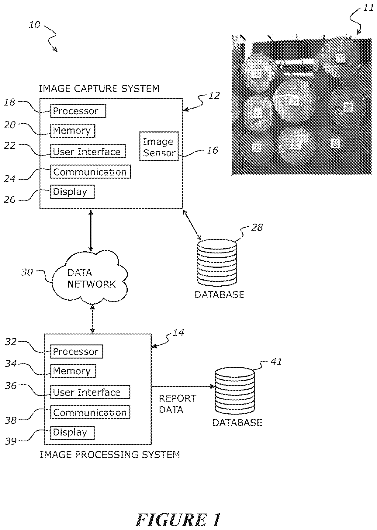
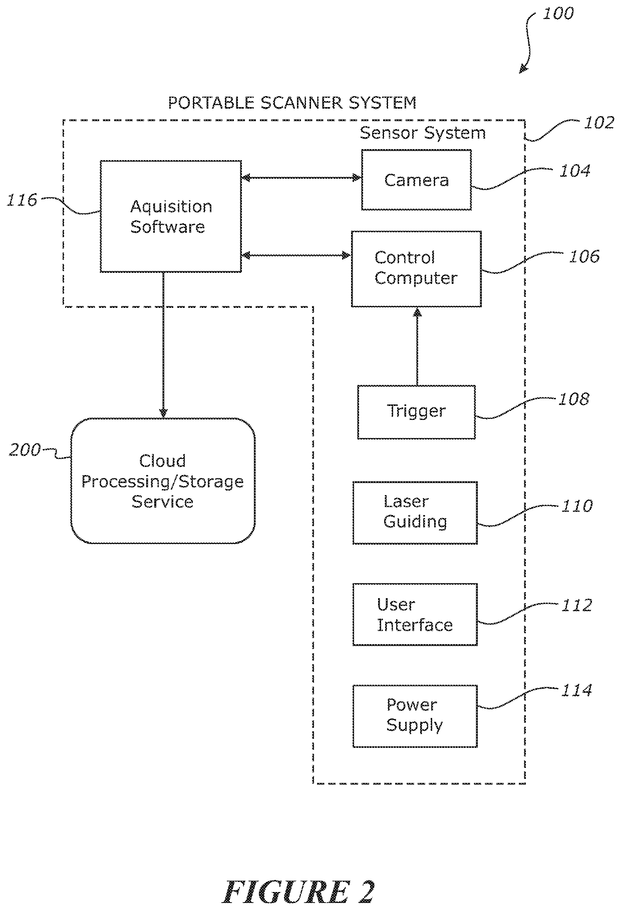
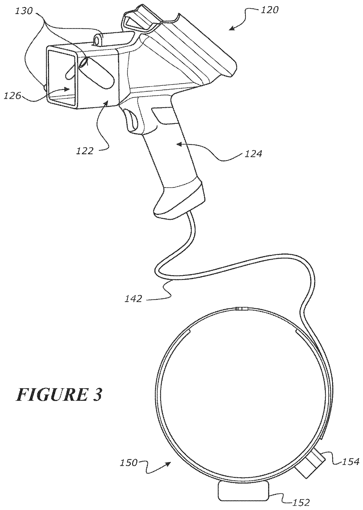
[0171]Referring to FIGS. 2-20, the first example embodiment of the log measurement system comprises an arrangement of an image capture system in the form of a handheld imaging assembly or handheld imaging device that is operated by an operator to capture individual log-end images of each log and a log pile or log load on the ground or more typically in situ on a log transport truck or vehicle.

[0172]2.2 Ticket Application to Log Ends

[0173]In this embodiment, reference objects or reference markers are provided on the end of each log to be measured. In this embodiment, the reference objects are in the form of a two-dimensional reference tag or ticket that is applied typically centrally on the log-end. In particular, the reference tag or ticket is applied to the surface of the small end of each log, typically centrally. The reference t...

second example embodiment

3. Handheld Imaging System for Image Acquisition, Using Depth Data for Scaling into Real-World Measurements

[0270]Referring to FIG. 21, a second example embodiment of the log measurement system 400 will be described. This second example embodiment log measurement system is similar to the first example embodiment but does not rely on a reference object (e.g. reference ticket) for any log-face plane perspective correction and / or measurement scale for transforming the pixel data of the log-end boundary into real-world co-ordinates or measurement units. The reference ticket may still be present on the log-end, and used for IDing the log and associating the extracted log-end measurements with the log ID code, but is not required for any perspective correction or scaling of the information into real-world measurement data.

[0271]In this second example embodiment of the log measurement system, depth data is captured for each log-end image, is used for any perspective correction and / or scalin...

third example embodiment

4. Robotic Imaging Assembly

[0282]In this alternative embodiment, the log measurement system may be configured to capture the log-end images (and the associated depth data for each image in the case of the second example embodiment) using a robotic scanner rather than a user manually imaging the log-ends with a portable handheld scanning or imaging unit. By way of example only, the digital camera or imaging sensor(s) or sensor system of the image capture system may be mounted to or carried by a robotic arm or robotic assembly that is operable to automatically to move the digital camera or image sensor(s) or sensor system sequentially or progressively adjacent each log-end of the logs in a log pile or log stack one at a time, and sequentially capture a log-end image of each log (and any associated depth data for each image in the case of the second example embodiment). As will be appreciated, the robotic assembly may be configured to operate next to a log pile or log stack provided on...


PUM


Abstract

A log measurement system for measuring individual logs, each log comprising a log-end face with an applied reference marker of known characteristics. The system includes an image capture system operable or configured to capture a digital image or images of the log-end face of a log to generate a log-end image capturing the log-end face and reference marker. The system also includes an image processing system that is operable or configured to process the captured log-end image to detect or identify the log-end boundary of the log and generate measurement data associated with the log-end boundary in real-world measurement units based on the known characteristics of the reference marker.

Description

FIELD OF THE INVENTION[0001]The invention relates to a measuring system which may be applied to measuring objects, including but not limited to a log measurement system for use in the forestry industry for log scaling.BACKGROUND TO THE INVENTION[0002]The log export industry in New Zealand and many other countries is required to count and barcode every log that is exported. After harvest, logs for export are typically delivered to a port on logging trucks or trailers. Upon arrival at the port, the load of logs on each truck is processed at a checkpoint or processing station. Typically, the number of logs in each load is counted and various measurements on each individual log are conducted to scale for volume and value, before being loaded onto ships for export.[0003]Depending on the country, log scaling can be carried out according to various standards.[0004]In New Zealand, almost all logs exported are sold on volume based on the Japanese Agricultural Standard (JAS). Scaling for JAS ...

Claims


Application Information

Patent Timeline
Patent Type & Authority Applications(United States)
IPC IPC(8): G06T7/62G01B11/08G06T7/143G01B11/00G01B11/02G06K7/14G06K7/10
CPCG01B11/022G06K7/10861G01B11/002G06K7/1417G01B11/08G06T7/143G06T7/62G06K7/1413G06K7/10722G06K7/1443G01B11/02G06Q10/08G06T7/187G06T2207/20164G01B11/24G06T7/12G06T2207/30108
Inventor MCIVER, GEOFFREY PETERREID, AARON BARRYHIRST, EVAN RYAN
Owner C 3 LIMITED
Why Eureka
Try Eureka