
Suture tensioning and securement device, system, and methods

Active Publication Date: 2020-09-10
SPEED CLIP SOLUTIONS LLC
View PDF0 Cites 0 Cited by
  • Summary
  • Abstract
  • Description
  • Claims
  • Application Information

AI Technical Summary

Benefits of technology

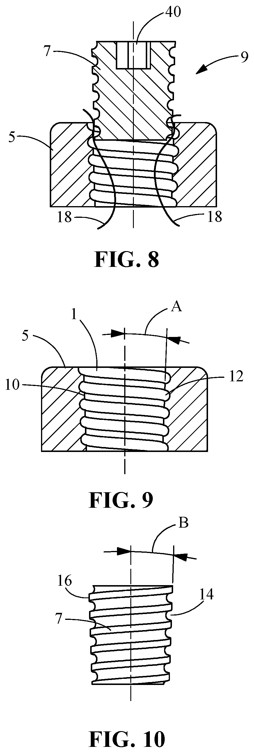
The present invention provides a suture clamp assembly with rounded lead in and out features that minimize deformation of suture leads when locked in place by a plug. The assembly also includes a gathering suture with a gathering loop and an optional anchor affixed to it. This invention allows for securement, tensioning, and clamping of one or more suture leads, including from at least one to twenty or more. The assembly is suitable for a range of surgical applications, including rotator cuff repair, labral repair, biceps tenodesis, acromioclavicular joint stabilization, and others.

Problems solved by technology

Despite these benefits, there are inefficiencies in the surgical suite in terms of substantially increased surgical time and implant cost by virtue of use of what may be twice as many suture anchors.
In addition, there may be unacceptable compromise to bone when multiple anchors are secured within the bone, for example in the tuberosity footprint, and / or there is poor bone stock to support anchor fixation.
Furthermore, where knotting of suture leads is employed to achieve fixation, there are inefficiencies in the surgical suite in terms of substantially increased surgical time due to the challenges of tying knots in many leads, and associated challenges which include lead breakage, and cuts to the surgeon's gloves and / or fingers.
Tying multiple suture leads in the operating room requires significant time and can lead to unsecured suture leads.
And many of the clip designs in the art apply sharp point loads to the suture material causing potential failure points in the suture lead.
The challenges are many for surgical procedures that involve securing soft tissue to bone, for example, in the context of a rotator cuff repair.

Method used


Image

  • Suture tensioning and securement device, system, and methods
  • Suture tensioning and securement device, system, and methods
  • Suture tensioning and securement device, system, and methods

Examples


Embodiment Construction

[0043]This description describes exemplary embodiments in accordance with the general inventive concepts and is not intended to limit the scope of the invention in any way. Indeed, the invention as described in the specification is broader than and unlimited by the exemplary embodiments set forth herein, and the terms used herein have their full ordinary meaning.

[0044]The general inventive concepts will now be described with occasional reference to the exemplary embodiments of the invention. Unless otherwise defined, all technical and scientific terms used herein have the same meaning as commonly understood by one of ordinary skill in the art encompassing the general inventive concepts. The terminology set forth in this detailed description is for describing particular embodiments only and is not intended to be limiting of the general inventive concepts.

[0045]As used herein, the singular forms “a,”“an,” and “the” are intended to include the plural forms as well, unless the context c...


PUM


Abstract

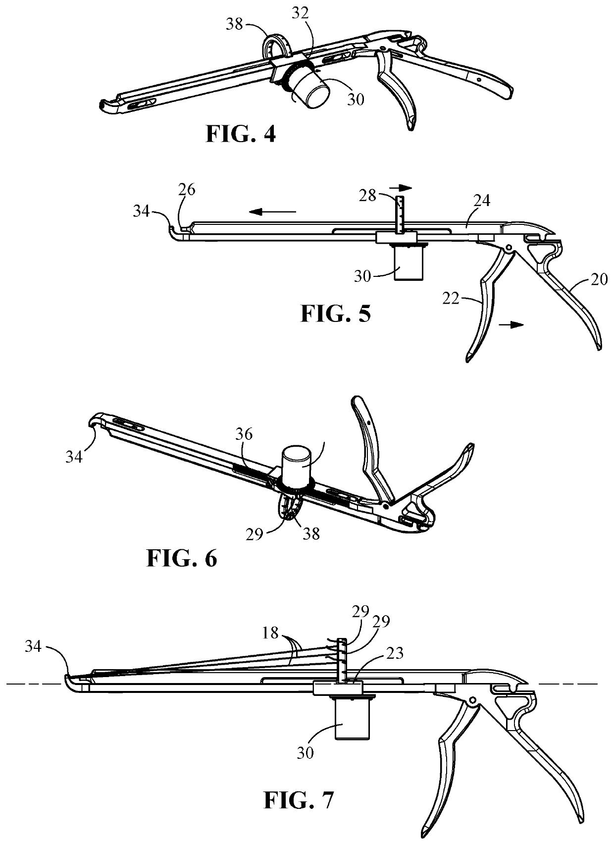
A system and methods for gathering, tensioning, and clamping a plurality of suture leads may be used for any of a range of possible surgical applications. The system includes a suture clamp assembly that includes receptacle and plug components, wherein suture leads passed into the receptacle are secured when the plug is inserted into the receptacle to lock the suture leads in place, a gathering suture that includes a gathering loop, an instrument for securement of the plurality of suture leads, and optionally an anchor affixed to the gathering suture. The system may be used to address rotator cuff repairs, labral repair, biceps tenodesis, acromioclavicular joint stabilization, and applications in other joints and bones within a body.

Description

PRIORITY[0001]The present application claims priority to and the claims the benefit of U.S. Provisional Patent Application Ser. No. 62 / 814,700, filed Mar. 6, 2019, 62 / 816,633, filed Mar. 11, 2019, and 62 / 863,383, filed Jun. 19, 2019, each with the title “SUTURE LOCK AND TENSION INSTRUMENT,” each of which is hereby incorporated by reference in its entirety.FIELD OF THE INVENTION[0002]Provided herein are suture tensioning and securement devices, system, and methods for securing two or more suture leads. The benefits realized include the ability to secure multiple suture leads to a single fixation point while minimizing or eliminating reliance on knotting any one or more of the suture leads.BACKGROUND OF THE INVENTION[0003]In the field of rotator cuff repair surgery transosseous fixation is considered the gold standard because it is shown to provide good and even excellent long-term outcomes for the patient and is demonstrated to provide suitable performance based on biomechanical stud...

Claims


Application Information

Patent Timeline
IPC IPC(8): A61B17/04
CPCA61B2017/0496A61B2017/044A61B17/0401A61B2017/0409A61F2/0811A61B17/0487A61B2017/0488A61B17/06166A61B2017/0417A61B2017/0464
Inventor KRUSE, KEVINBINDER, LAWRENCE
Owner SPEED CLIP SOLUTIONS LLC
Learn More