Prosthetic Heart Valve And Methods For Cardiac Hemodynamic Optimization And Monitoring

a heart valve and prosthesis technology, applied in the field of prosthetic heart valves, and devices and methods for cardiac hemodynamic optimization and monitoring, can solve problems such as wear and tear, exacerbate lvot interruption problems, and the entire circulatory system

Active Publication Date: 2020-09-10
TENDYNE HLDG
View PDF0 Cites 8 Cited by
  • Summary
  • Abstract
  • Description
  • Claims
  • Application Information

AI Technical Summary

Problems solved by technology

These valves open and close constantly, and as such, can be subject to wear and tear and other challenges that affect their performance (e.g., mitral valve regurgitation, prolapse, and / or stenosis), and consequently, the entire circulatory system.
Prosthetic heart mitral valve implantation, however, can be associated with displacement of the native mitral valve apparatus and / or interference or obstruction with the LVOT (i.e., interference with blood flow out of the left ventricle of the heart).
As another example, some patients' anatomy is not conducive to prosthetic valve implantation while sufficiently preserving the LVOT, and in some instances, can exacerbate LVOT interruption issues.
In some instances, a septal bump alone or in combination with an implanted prosthetic mitral valve can reduce the LVOT such that an undesirable fluid flow profile (e.g., a fluid jet) can occur from the left ventricle to the aorta.
Ablation, however, may include an invasive procedure, introduce additional risks to the patient, and / or undesirably permanently alter the heart.
Further, LVOT interruption (e.g., with a prosthetic mitral valve implanted within the heart) often includes an undesirable flow gradient within the LVOT and often requires one or more additional procedures to remove the prosthetic mitral valve or correct or recover the LVOT, or in some cases requires additional medication.
Even further, notwithstanding LVOT interruption, some patients with prosthetic mitral valve implants experience other problems associated with mitral valve replacement.

Method used


Image

  • Prosthetic Heart Valve And Methods For Cardiac Hemodynamic Optimization And Monitoring
  • Prosthetic Heart Valve And Methods For Cardiac Hemodynamic Optimization And Monitoring
  • Prosthetic Heart Valve And Methods For Cardiac Hemodynamic Optimization And Monitoring

Examples


Embodiment Construction

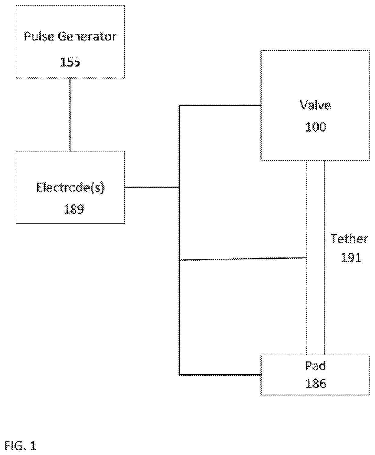
[0024]Apparatus, systems, and methods are described herein for inhibiting, limiting and / or preventing LVOT interruption and / or obstruction in conjunction with an implanted prosthetic valve (e.g., an implanted prosthetic mitral valve) having a tether extending from the implanted prosthetic valve through the left ventricle and out an incision in the apical region of the heart. The tether can aid in holding the implanted prosthetic valve in place in the native valve annulus (the prosthetic valve and the tether are referred to herein collectively as a “valve-tether”). In some embodiments, with the valve-tether implanted within the native annulus of the heart, an artificial electrical pulse generator (e.g, pacemaker) may be used to supplement the heart's natural conduction system (as described in more detail below) to manipulate the geometry and / or function of the heart such that LVOT interruption or obstruction is limited, prevented, or otherwise inhibited. In such embodiments, the valv...


PUM


Abstract

In some embodiments, a method includes delivering to a native valve annulus (e.g., a native mitral valve annulus) of a heart a prosthetic heart valve (200) having a body (242) expandable from a collapsed, delivery configuration to an expanded, deployed configuration. The method can further include, after the delivering, causing the prosthetic heart valve to move from the delivery configuration to the deployed configuration. With the prosthetic heart valve in its deployed configuration, an anchoring tether (191) extending from the prosthetic heart valve can be secured to a wall (Vw) of the heart (H). An electrode (189) coupled to at least one of the prosthetic heart valve or the anchoring tether can then be used to at least one of pace the heart or sense a signal associated with the heart.

Description

CROSS-REFERENCE TO RELATED APPLICATIONS[0001]The present application claims the benefit of U.S. Patent Application No. 62 / 592,716, filed Nov. 30, 2017, entitled PROSTHETIC HEART VALVE AND METHODS FOR CARDIAC HEMODYNAMIC OPTIMIZATION AND MONITORING, the disclosure of which is hereby incorporated herein by reference.BACKGROUND OF THE DISCLOSURE[0002]Embodiments described herein relate generally to prosthetic heart valves, and devices and methods for cardiac hemodynamic optimization and monitoring. More particularly, embodiments described herein relate to devices and methods for cardiac hemodynamic optimization and monitoring of patients having an implanted prosthetic heart valve.[0003]The human heart is responsible for pumping blood around the human body. The human heart is separated into four distinct chambers, and is commonly referenced in terms of the right or left side of the heart. The right side of the heart, including the right atrium and the right ventricle, is responsible for...

Claims


Application Information

Patent Timeline
Patent Type & Authority Applications(United States)
IPC IPC(8): A61N1/05A61F2/24A61N1/37A61N1/362
CPCA61F2250/0004A61N1/059A61N1/37A61F2/24A61N1/3629A61F2/2418A61F2/2457A61B5/287A61B5/686
Inventor CAPEK, JOHN M.URICK, MICHAEL J.
Owner TENDYNE HLDG
Why Eureka
Try Eureka