Cryotherapy device flow control

a flow control and cryotherapy technology, applied in the field ofablation, can solve the problems of no known cryotherapy device, significant visualization difficulty, and inability to achieve ablation effect,

Pending Publication Date: 2020-09-24
VESSI MEDICAL LTD
View PDF1 Cites 10 Cited by
  • Summary
  • Abstract
  • Description
  • Claims
  • Application Information

AI Technical Summary

Benefits of technology

[0034]at least one purge flow regulator on a purge inflow path partly overlapping with said cryo inflow path, configured to allow a low-pressure purge fluid flow through said cryo inflow path into said body lumen when said cryogenic fluid flow is stopped thereby reducing backflow into said cryo inflow path from said lumen.
[0058]Example 39. The method of any one of examples 37 or 38, comprising purging low-pressure fluid through said cryo inflow path and said cryo nozzle to prevent clogging of said cryo nozzle after said regulating.
[0120]According to some embodiments, a distal end of the cryotherapy device includes a swiveling component comprising at least one inflow nozzle, wherein the cryo fluid is injected through the inflow nozzle, which swivels together with the swiveling component, thereby assist with the coverage of an area or a volume with the cryo fluid.

Problems solved by technology

There are no known cryotherapy devices that are inserted into body lumen through an endoscope's working channel.
The main differences between current GI devices to those required for body lumens treatments are the size of the necessary insertion cavity (esophagus or colon are significantly bigger in diameter), the need for sensing and closed-loop pressure control in order to keep lumen open while avoiding over-pressure, and the need to deal with moisture and even remaining liquids that may interfere with ablation efficacy and may add significant visualization difficulties.
Known aspiration channels do not have the ability to control lumen volume or pressure due to the lack of sensing means and appropriate control mechanisms.
In addition the distance of the nozzle from the targeted area is not well-defined so as a result, the treatment outcome is not predictable and it may be difficult for the physician to follow the cryosurgery protocol.
There is no known use for cryotherapy devices in combination with immune modulation therapy within a body lumen, either using an endoscope or not.

Method used


Image

  • Cryotherapy device flow control
  • Cryotherapy device flow control
  • Cryotherapy device flow control

Examples


example 2

[0016] The system of example 1, comprising:

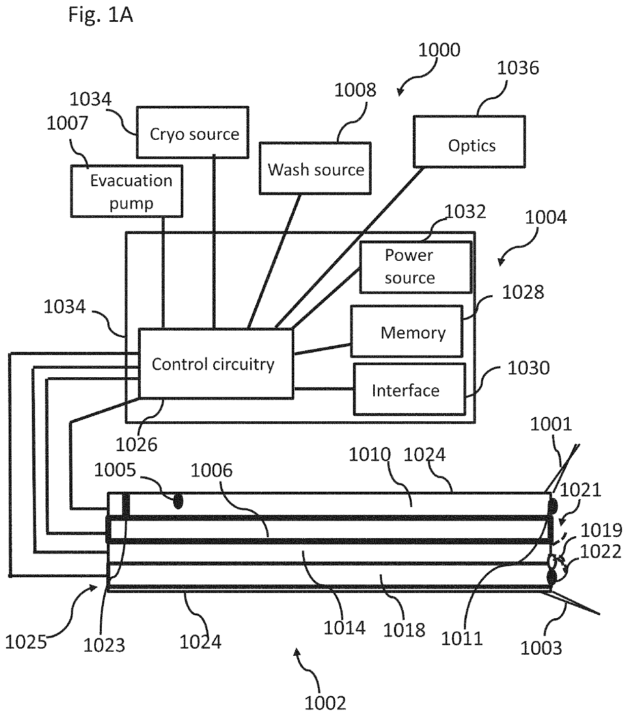
at least one cryo flow regulator on said cryo inflow path, configured to control flow of said cryogenic fluid through said cryo inflow path into said body lumen;

a control unit connected to said cryotherapy device, comprising:

[0017]a control circuitry connected to said at least one cryo flow regulator, configured to control said cryogenic fluid flow into said body lumen by transmitting a signal to said cryo flow regulator.

[0018]Example 3. The system of example 2, comprising at least one washing flow regulator on said washing inflow path connected to said control circuitry, and wherein said washing flow regulator controls flow through said washing inflow path in response to a signal from said control circuitry.

example 4

[0019] The system of example 3, wherein said control circuitry signals said washing flow regulator to regulate washing flow into said body lumen when cryogenic flow is stopped.

example 5

[0020] The system of example 2, comprising at least one purge flow regulator on said cryo inflow path connected to said control circuitry, configured to control low-pressure fluid flow through said cryo inflow path when said cryogenic flow from said cryogenic fluid source is stopped.


PUM


Abstract

A cryotherapy system, including, an elongated cryotherapy device having a proximal end and a distal end shaped and sized to be positioned inside a body lumen, including:a cryo inflow path fluidically connecting a cryogenic fluid source with the distal end of the cryotherapy device, wherein the cryo inflow path is configured to allow cryogenic flow from the cryogenic fluid source into the body lumen;an optics assembly configured to visualize a field of view between the distal end and a target region inside the body lumen;a washing inflow path fluidically connecting a washing fluid source with at least one washing opening configured to aim washing fluid towards the optics assembly in the distal end and / or towards the field of view.

Description

RELATED APPLICATION[0001]This application claims the benefit of priority under 35 USC § 119(e) of U.S. Provisional Patent Application No. 62 / 454,753 filed 4 Feb. 2017, the contents of which are incorporated herein by reference in their entirety.FIELD AND BACKGROUND OF THE INVENTION[0002]The present invention, in some embodiments thereof, relates to ablation, including cryoablation, cryosurgery or cryotherapy devices and, more particularly, but not exclusively, to cryotherapy of body lumen diseases.[0003]Cryoablation, cryosurgery or cryotherapy is a technique by which targeted areas, which may include undesired symptoms, lesions, or free nerve endings are destroyed or ablated by freezing. Tissue destruction by freezing includes direct injury to cells caused by ice crystal formation, as well as delayed injury that may be caused by apoptosis (regulated cells death) and / or vascular effects.[0004]Cryotherapy is performed by utilizing a pressurized coolant (such as CO2, LN2, and / or nitrou...

Claims


Application Information

Patent Timeline
Patent Type & Authority Applications(United States)
IPC IPC(8): A61B18/02A61B90/00
CPCA61B18/02A61B2090/064A61B2018/0212A61B2018/00791A61B2218/007A61B2018/00744A61B90/06A61B2218/002A61B2018/00982A61B2018/0262A61B2018/00863A61B2018/00517A61B2018/00559A61B2018/00648A61B1/126A61B1/015A61B18/0218
Inventor KOCHAVI, EYAL
Owner VESSI MEDICAL LTD
Why Eureka
Try Eureka