Rotating electric device

a rotating electric device and electric motor technology, applied in the direction of applying/manufacturing slot closures, magnetic circuit rotating parts, magnetic circuit shape/form/construction, etc., can solve the problems of deteriorating productivity, narrowing of winding space, etc., to improve the output power per weight of the rotating electric device, improve the effect of power generation area and increase of power generation area

Active Publication Date: 2020-09-24
VAM CO LTD
View PDF0 Cites 5 Cited by
  • Summary
  • Abstract
  • Description
  • Claims
  • Application Information

AI Technical Summary

Benefits of technology

[0040]The rotating electric device according to the present invention, i.e., the electric motor or the generator may include the plurality of winding slots formed at the predetermined interval in the circumferential direction and the inner and outer stators, each of which has one or more iron slots that are concave at the relatively protruding portion by the pair of winding slots adjacent to each other to significantly improve the output power per weight of the rotating electric device.
[0041]In addition, in the rotating electric device, the electric motor, or the generator according to the present invention, the outer and inner stators may be respectively disposed inside and outside the rotor to increase in power generation area, thereby significantly improving the output power per weight of the rotating electric device.
[0042]Furthermore, the magnetic flux of the outer stator may well pass through the rotor to the inner stator

Problems solved by technology

As a result, a space for the winding may

Method used


Image

  • Rotating electric device
  • Rotating electric device
  • Rotating electric device

Examples


first embodiment

1. First Embodiment

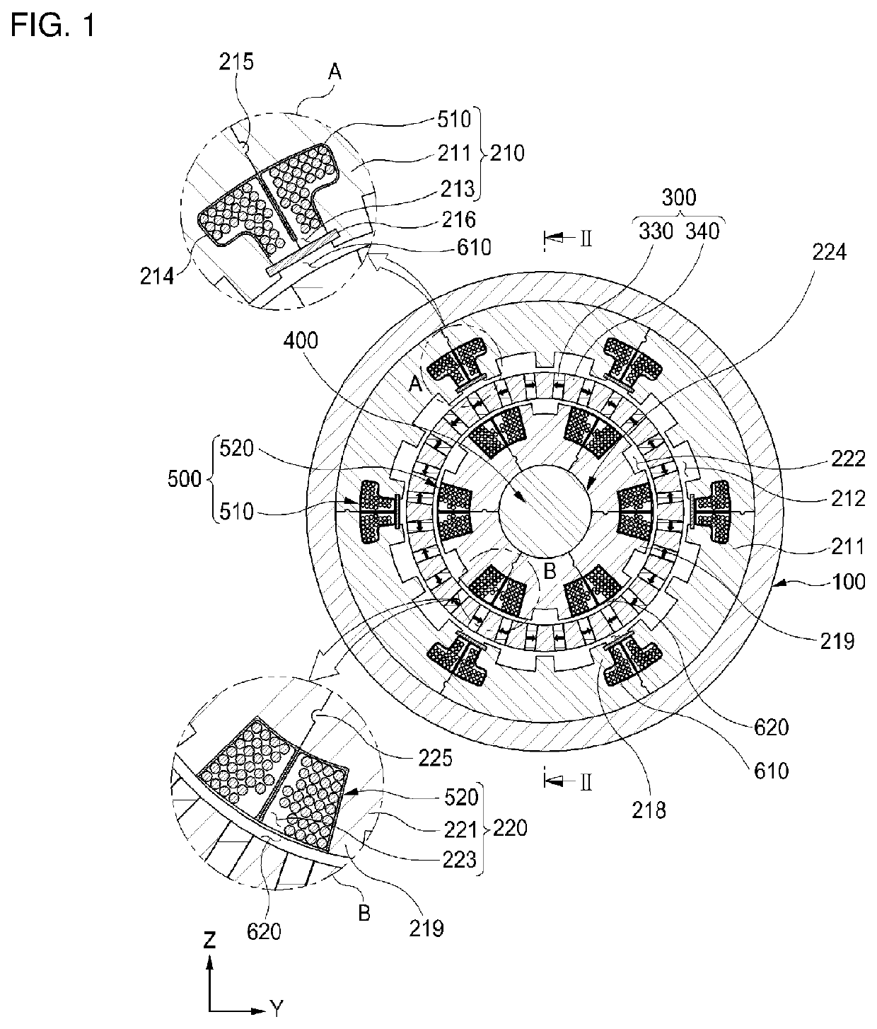
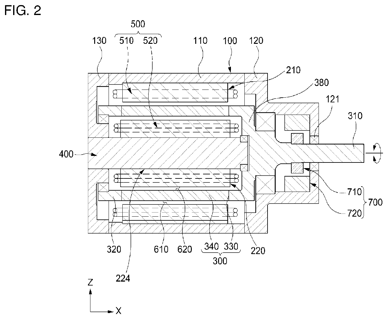
[0062]As illustrated in FIGS. 1 and 2, an electric motor according to a first embodiment of the present invention includes an outer stator 210, an inner stator 220, and a rotor 300.

[0063]Outer Stator

[0064]The outer stator 210 may include an outer stator iron core 211 in which a plurality of outer stator winding slots 213 are defined in an inner circumferential surface thereof at a predetermined interval in a circumferential direction and an outer winding 510 wound with respect to outer stator iron core teeth 218 that are relatively disposed by the outer stator winding slots 213 adjacent to each other and also may be variously configured.

[0065]The outer stator iron core 211 may be configured so that the plurality of outer stator winding slots 213 are defined in the inner circumferential surface thereof at a predetermined interval in the circumferential direction and also may be variously configured.

[0066]Here, the outer stator winding slots 213 may be grooves that ...

second embodiment

2. Second Embodiment

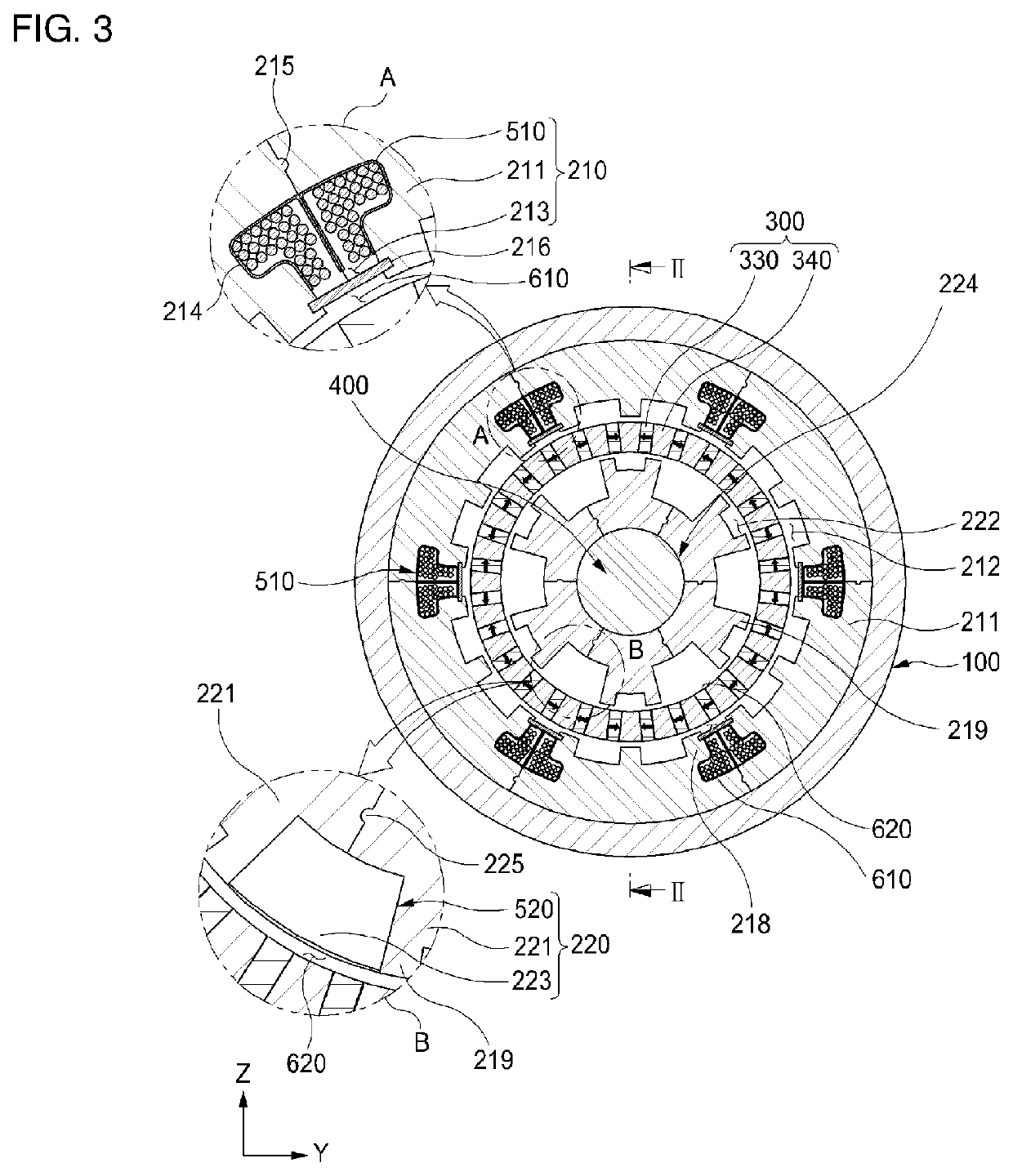
[0135]With respect to the configuration of the inner stator 220, although the configuration including the inner stator iron core 221 and the inner winding 520 wound around the inner stator iron core 221 is described in the embodiment of FIGS. 1 and 2, various modifications may be possible such as a configuration in which the inner winding 520 is not wound. For example, when the electric motor has a small diameter, a winding operation of the inner winding 520 may be difficult, and the number of coils to be wound may be very small, and thus, it may be hardly expected to increase in output torque (an amount of power to be generated).

[0136]That is, as illustrated in FIGS. 3 and 4, in an electric motor according to a second embodiment of the present invention, the inner stator 220 may be constituted by only the iron cores without the inner winding 520 in the configuration according to the first embodiment of the present invention.

[0137]In summary, FIGS. 1 and 2 illust...


PUM


Abstract

A rotating electric device comprising: an outer stator (210) comprising an outer stator iron core (211) having a plurality of outer stator winding slots (213) formed on the inner peripheral surface thereof at a predetermined interval in the circumferential direction, and an outer winding (510) wound around an outer stator iron core tooth (218) relatively formed by a pair of outer stator winding slots (213) adjacent to each other; an inner stator (220) comprising an inner stator iron core (221) having a plurality of inner stator winding slots (223) formed on the outer peripheral surface thereof at a predetermined interval in the circumferential direction; and a rotor (300) having, between the outer stator (210) and the inner stator (220).

Description

TECHNICAL FIELD[0001]The present invention relates to a rotating electric device such as an electric motor or a generator.BACKGROUND ART[0002]In recent years, as interest in transport units using electricity is increasing, electric vehicles, electric bicycles, electric two-wheeled vehicles, and tricycles have been commercialized. In addition, high outputs of electric motors in robot fields for factory automation and generators for generating electricity in industries are required, and thus, efforts for achieving miniaturization and price competitiveness are increasing.[0003]Particularly, when electric motors that are essentially mounted on the transport units and the robots, which using electricity, are installed in a transfer body, a high output is required while having a small size, and mass production of high-power small electric motors and generators (electric devices) is required.[0004]However, each of iron cores of the electric motors and the generators according to the relate...

Claims


Application Information

Patent Timeline
IPC IPC(8): H02K1/16H02K1/27H02K3/48H02K11/21H02K7/00
CPCH02K3/48H02K11/21H02K1/16H02K7/003H02K1/2793H02K16/04H02K7/083H02K1/148H02K21/14H02K21/16H02K21/22H02K1/2773H02K7/088H02K3/28H02K15/0018H02K1/2796Y02T10/64H02K1/165H02K1/276H02K1/14H02K3/12H02K2201/03
Inventor KANG, DOHYUNWOO, BYUNG CHULHWANG, WOOK
Owner VAM CO LTD
Why Eureka
Try Eureka