Inductor bridge and electronic device

a technology of electronic devices and bridges, applied in the field ofinductor, can solve the problems of poor connection between the joining portion and the circuit portion, the inductance of the circuit and the inductance of the inductance of the coil is significantly reduced or prevented. , to achieve the effect of increasing the connection reliability, reducing the deviation of the inductance of the coil, and high connection reliability

Active Publication Date: 2020-09-24
MURATA MFG CO LTD
View PDF0 Cites 0 Cited by
  • Summary
  • Abstract
  • Description
  • Claims
  • Application Information

AI Technical Summary

Benefits of technology

[0015]With the above configuration, an electronic device including an inductor bridge with high connection reliability at the joining portion is able to be provided. Further, an electronic device including an inductor bridge in which the deviation of the inductance of the coil is significantly reduced or prevented is able to be provided.
[0016]According to preferred embodiments the present invention, inductor bridges th

Problems solved by technology

When the flexible inductor bridge is mounted on a circuit board or the like, due to a structure in which the inductor bridge is arranged in a limited space, the inductor bridge not only merely has

Method used


Image

  • Inductor bridge and electronic device
  • Inductor bridge and electronic device
  • Inductor bridge and electronic device

Examples


first preferred embodiment

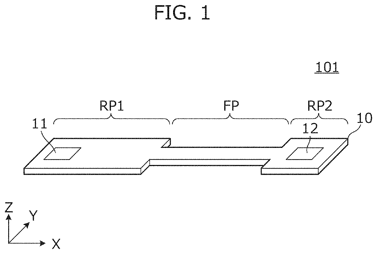
[0027]FIG. 1 is an external perspective view of an inductor bridge 101 according to a first preferred embodiment of the present invention. The inductor bridge 101 includes a flexible substrate 10 and a coil defined by a conductor pattern provided on or in the flexible substrate 10, and connects a plurality of circuit portions.

[0028]The flexible substrate 10 includes wide rigid portions RP1 and RP2 and a narrow flexible portion FP. That is, the rigid portions RP1 and RP2 are wider than the flexible portion FP. In FIG. 1, the direction along the Y axis is the width direction. A first joining portion 11 is provided on the rigid portion RP1 of the inductor bridge 101, and a second joining portion 12 is provided on the rigid portion RP2.

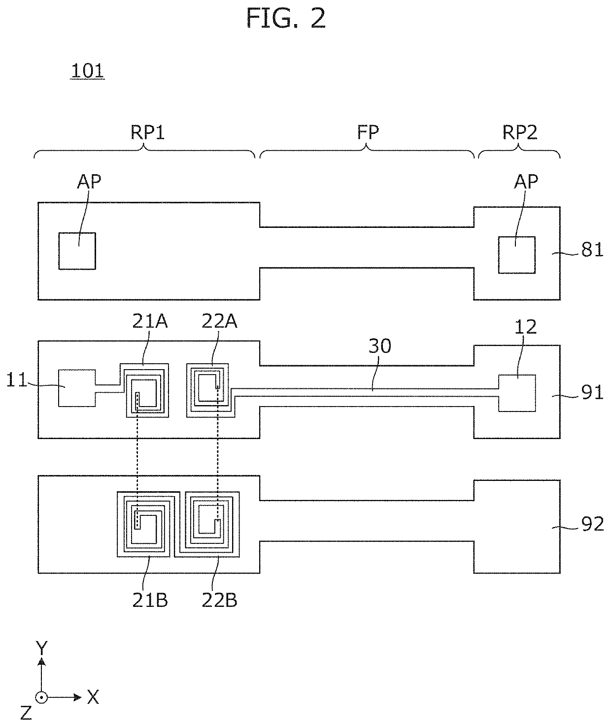
[0029]FIG. 2 is a plan view of each layer of the inductor bridge 101. The inductor bridge 101 includes insulating base material layers 91 and 92 and a resist film 81. On the insulating base material layer 91, a first joining portion 11, a first coil porti...

second preferred embodiment

[0036]In a second preferred embodiment of the present invention, an example of an inductor bridge including a coil different from that of the first preferred embodiment will be described.

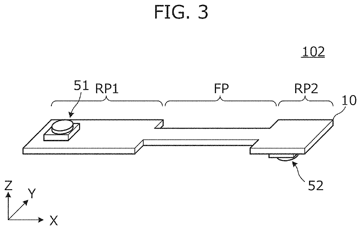
[0037]FIG. 3 is an external perspective view of the inductor bridge 102 according to the second preferred embodiment. The inductor bridge 102 includes a flexible substrate 10 and a coil defined by a conductor pattern provided on or in the flexible substrate 10, and connects two circuit portions. The inductor bridge 102 includes connectors 51 and 52. The connector 51 is joined to a first joining portion, which will be described later. The connector 52 is joined to a second joining portion, which will be described later.

[0038]FIG. 4 is a plan view of each layer of the inductor bridge 102. The inductor bridge 102 includes insulating base material layers 91 and 92 and resist films 81 and 82. A first joining portion 11, a first coil portion 21A, and a second coil portion 22A are provided in the rigid por...

third preferred embodiment

[0048]In a third preferred embodiment of the present invention, an example of an inductor bridge including a coil that is different from that of the first and second preferred embodiments will be described.

[0049]FIG. 7 is a plan view of each layer of an inductor bridge according to the third preferred embodiment. Further, FIG. 8 is a longitudinal cross-sectional view of the inductor bridge 103. The inductor bridge 103 includes insulating base material layers 91, 92, 93 and 94. A first joining portion 11, a first coil portion 21A, and a second coil portion 22A are provided in a rigid portion RP of the insulating base material layer 91. An internal electrode 11S of a first joining portion, a first coil portion 21B, and a second coil portion 22B are provided in a rigid portion RP of the insulating base material layer 92. An internal electrode 11S of a first joining portion, a first coil portion 21C, and a second coil portion 22C are provided in a rigid portion RP of the insulating base...


PUM

PropertyMeasurementUnit
Flexibilityaaaaaaaaaa
Magnetic fluxaaaaaaaaaa

Abstract

An inductor bridge includes a flexible substrate and a coil defined by a conductor pattern provided on or in the flexible substrate, and connects a plurality of circuit portions. The flexible substrate includes a rigid portion and a flexible portion, the rigid portion being wider than the flexible portion. The rigid portion includes the coil and a joining portion connected to another circuit. The coil includes two coil portions located at different positions in plan view, a flexible portion is located adjacent to one side of the rigid portion, and at least two coil portions of the plurality of coil portions are located on the one side when viewed from the joining portion.

Description

CROSS REFERENCE TO RELATED APPLICATIONS[0001]This application claims the benefit of priority to Japanese Patent Application No. 2017-250243 filed on Dec. 26, 2017 and is a Continuation Application of PCT Application No. PCT / JP2018 / 047445 filed on Dec. 25, 2018. The entire contents of each application are hereby incorporated herein by reference.BACKGROUND OF THE INVENTION1. Field of the Invention[0002]The present invention relates to an element that connects two circuit portions, and more particularly, to an inductor bridge including an inductance component and an electronic device including the inductor bridge.2. Description of the Related Art[0003]Conventionally, when a small electronic device such as a mobile terminal includes a circuit portion provided on a circuit board or the like and a circuit portion such as an antenna provided by a member different from the circuit board, the circuit portions are sometimes connected via a flexible inductor bridge as indicated, for example, i...

Claims


Application Information

Patent Timeline
IPC IPC(8): H05K1/02H05K1/16H05K1/03H05K1/18H01F17/00H01Q1/38
CPCH05K2201/10015H05K1/165H05K1/0393H05K1/0278H05K2201/0141H01F17/0013H05K1/189H05K2201/0158H01Q1/38H01F2017/006H01F17/0006H01F2017/0046H05K1/028H05K1/147H05K2201/10098H05K1/117
Inventor HASHIMOTO, TAKUYAYAMAMOTO, MASAYOSHI
Owner MURATA MFG CO LTD
Why Eureka
Try Eureka