Flexible substrate and method for fabricating the same

Inactive Publication Date: 2020-09-24
PHOENIX PIONEER TECH
View PDF1 Cites 3 Cited by
  • Summary
  • Abstract
  • Description
  • Claims
  • Application Information

AI Technical Summary

Benefits of technology

The present invention improves the circuit density and reduces the thickness of rigid-flexible board structures by adding additional elements and substrate structures that are different from previous designs. This is useful for high-end mobile devices that require reduced thicknesses and complicated circuits.

Problems solved by technology

However, the soft board 10 and the rigid boards 11 cannot be aligned accurately due to great interlayer size variations of the soft board 10 and limitations of the attachment process.
But it cannot meet the fine pitch requirement.
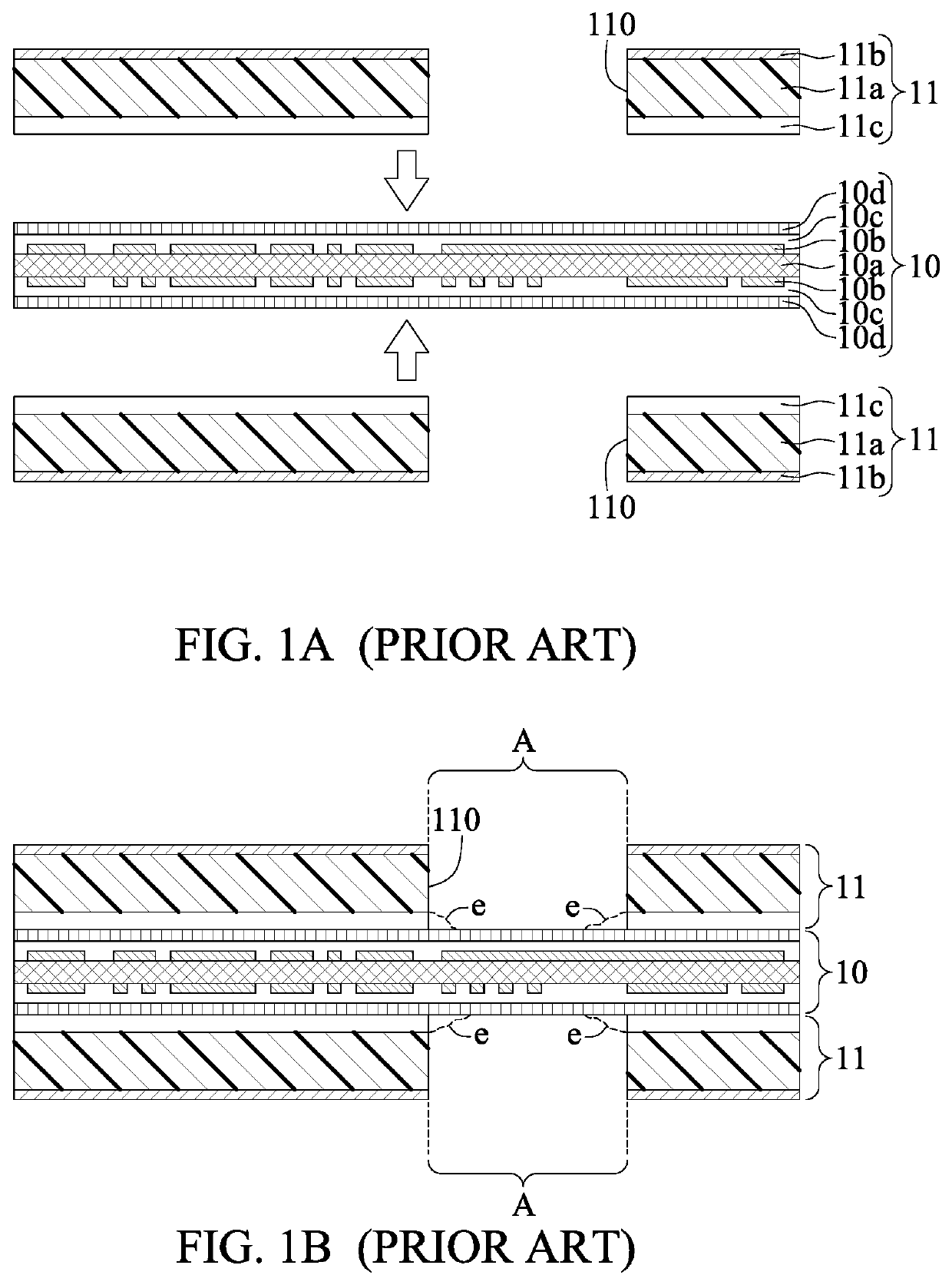
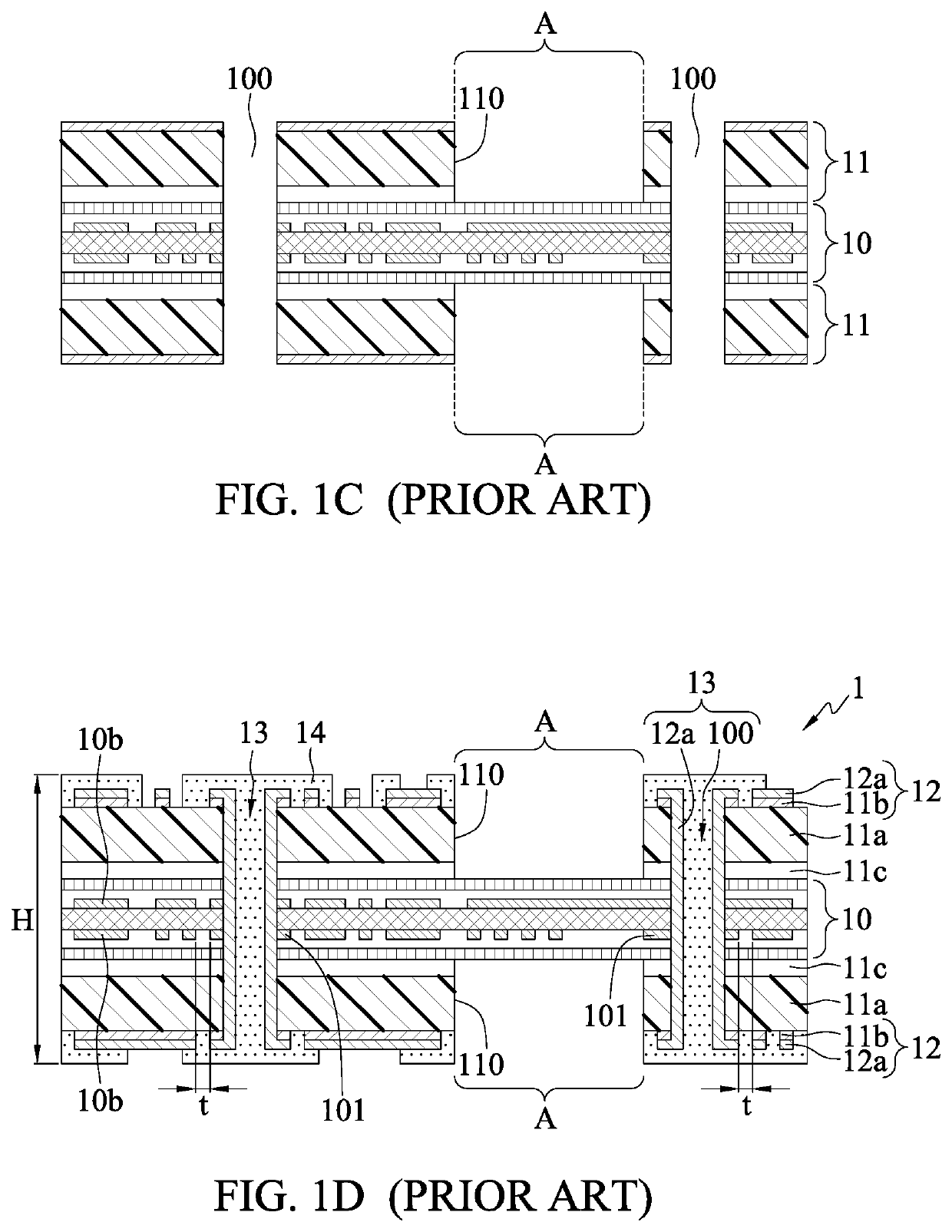
Further, since the rigid boards 11 are attached to the soft board 10 through the pure adhesive layer 11c, defects such as adhesive overflows e (at corners of the through holes 110 of FIG. 1B), shorts or edge sinks may occur at interfaces between the soft board 10 and the rigid boards 11, thus adversely affecting the subsequent attachment process and the flexibility of the packaging substrate.
Therefore, the packaging substrate 1 cannot meet the thinning requirement.
But it cannot meet the fine pitch requirement.
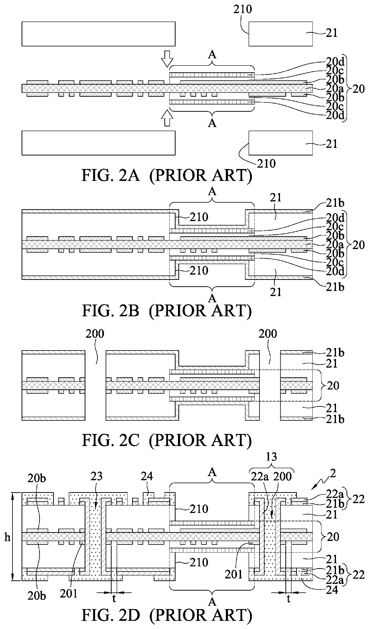
Further, after lamination of the dielectric layer 21, the rigid-flexible interface of the packaging substrate 2 may bulge due to the existence of two kinds of materials (the dielectric layer 21 of prepreg and the protection film 20d), thus adversely affecting the subsequent attachment process and the flexibility of the packaging substrate.
Therefore, the packaging substrate 2 cannot meet the thinning requirement.
Further, after lamination of the dielectric layers 31d, an edge bulge or prepreg overflow may occur at the rigid-flexible interface of the packaging substrate 3 due to the existence of two kinds of materials (the dielectric layers 3d1 and the protection films 30d), thus adversely affecting the subsequent attachment process and the flexibility of the packaging substrate.
Therefore, the packaging substrate 3 cannot meet the thinning requirement
As such, the subsequent attachment process and the flexibility of the packaging substrate are adversely affected.

Method used


Image

  • Flexible substrate and method for fabricating the same
  • Flexible substrate and method for fabricating the same
  • Flexible substrate and method for fabricating the same

Examples


Embodiment Construction

[0060]The following illustrative embodiments are provided to illustrate the disclosure of the present disclosure, these and other advantages and effects can be apparent to those in the art after reading this specification. It should be noted that all the drawings are not intended to limit the present disclosure.

[0061]Various modifications and variations can be made without departing from the spirit of the present disclosure. Further, terms such as “first”, “second”, “on”, “a” etc. are merely for illustrative purposes and should not be construed to limit the scope of the present disclosure.

[0062]FIGS. 5A to 5F are schematic cross-sectional views showing a method for fabricating a flexible substrate 5 according to a first embodiment of the present disclosure.

[0063]Referring to FIG. 5A, a plurality of first conductive posts 51 and a block 59a are disposed on a carrier 50 through a patterning process.

[0064]In an embodiment, the carrier 50 is metal, a semiconductor or an insulating subst...


PUM


Abstract

A flexible substrate is provided, including a coreless substrate body having a flexible section, and an additional element formed on the substrate body and having a through hole exposing the flexible section, thereby reducing the overall thickness of the flexible substrate and meeting the thinning requirement

Description

BACKGROUND1. Technical Field The present disclosure relates to packaging substrates, and, more particularly, to a flexible substrate and a method for fabricating the same.2. Description of Related Art[0001]Currently, rigid-flexible circuit boards are widely applied in smartphone boards, optoelectronic boards, CMOS, battery modules and wearable devices. In a conventional rigid-flexible circuit board, a soft board structure is encapsulated by a rigid board structure, a portion of the soft board structure that needs to be flexed is exposed from the rigid board structure, and interlayer connections are used to replace conventional surface mounting, thereby saving spaces, simplifying the assembly process and effectively reducing noises transmitted from the soft board structure to the rigid board structure.[0002]Therefore, the application of rigid-flexible circuit boards in electronic products (especially in lighter, thinner, shorter and smaller mobile devices and wearable devices) is rap...

Claims


Application Information

Patent Timeline
IPC IPC(8): H05K3/46H05K1/02
CPCH05K1/0278H05K3/4691H05K2203/308H05K3/4647H05K3/4682
Inventor YU, CHUN-HSIENTSAI, HSIEN-MING
Owner PHOENIX PIONEER TECH
Why Eureka
Try Eureka