Pneumatic pump silencer, pneumatic pump comprising such a silencer and coating product spraying installation comprising at least one such pneumatic pump

Active Publication Date: 2020-10-01
EXCEL IND INC
View PDF0 Cites 0 Cited by
  • Summary
  • Abstract
  • Description
  • Claims
  • Application Information

AI Technical Summary

Benefits of technology

[0007]The invention more specifically aims to address this problem, by proposing a pneumatic pump silencer preventing the accumulation of cond

Problems solved by technology

When a chamber is connected to the air exhaust, the compressed air leaving the pneumatic motor is not directly released into the open air, since the abrupt expansion of the compressed air would cause significant noise nuisances, due to the fact that, in general, the compressed air is not yet at atmospheric pressure.
These silencers remain relatively cumbersome and cannot be integrated within a cover of the pne

Method used


Image

  • Pneumatic pump silencer, pneumatic pump comprising such a silencer and coating product spraying installation comprising at least one such pneumatic pump
  • Pneumatic pump silencer, pneumatic pump comprising such a silencer and coating product spraying installation comprising at least one such pneumatic pump
  • Pneumatic pump silencer, pneumatic pump comprising such a silencer and coating product spraying installation comprising at least one such pneumatic pump

Examples


Example

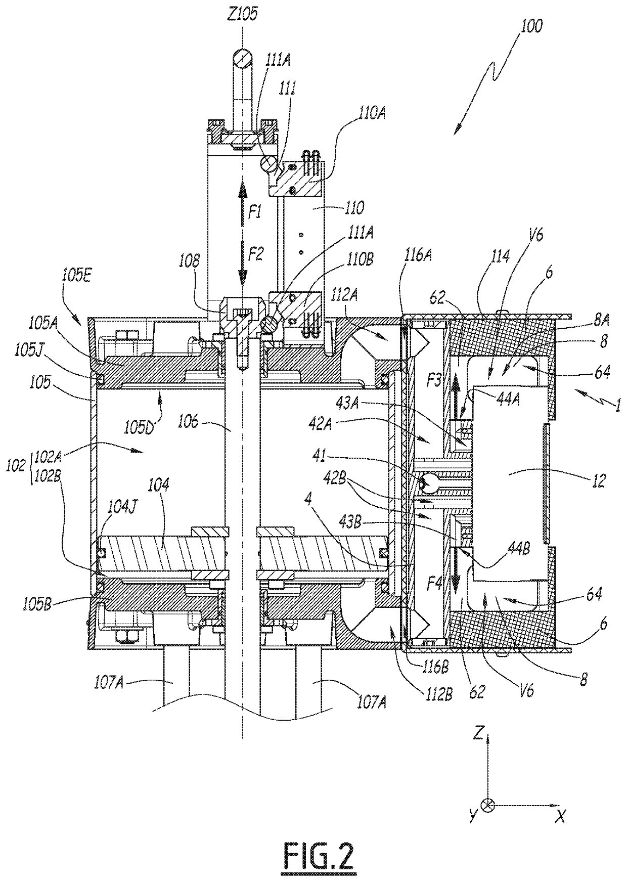
[0031]A same direct orthonormal coordinate system XYZ is shown in each of the figures, and the “top” and “bottom” directions for the interpretation of terms such as “top”, “bottom”, “upper”, “lower”, “below” are directions that are to be considered along axis Z and corresponding to a mounted configuration of the pneumatic pump or its component elements.

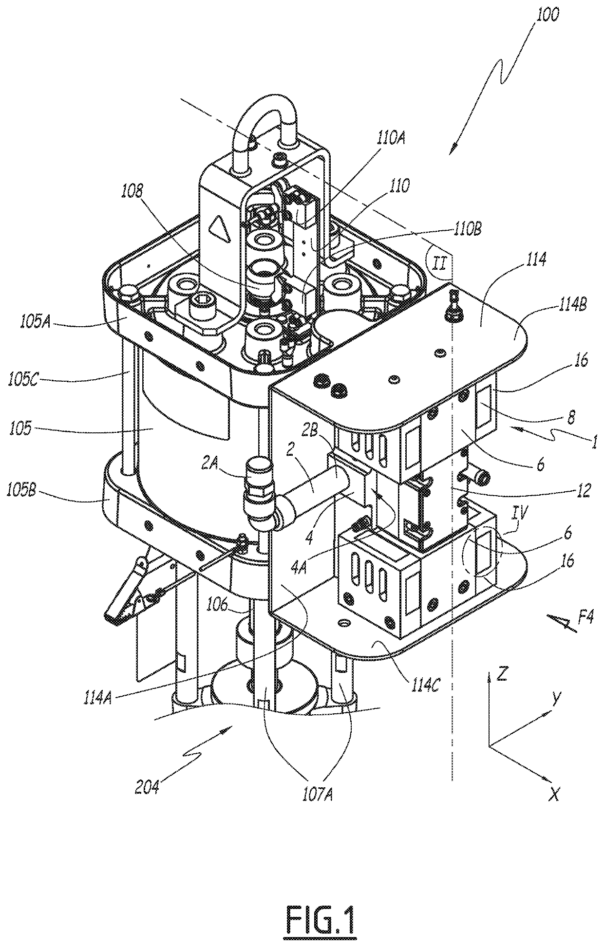
[0032]A pneumatic pump 100 is shown in FIG. 1. Pneumatic pump 100 is shown in the mounted configuration, certain elements having been omitted to facilitate the understanding of the operation of pneumatic pump 100.

[0033]Pneumatic pump 100 includes a pump cylinder 105 with a circular section and oriented along an axis Z105 parallel to axis Z.

[0034]Pump cylinder 105 is closed, at one end, by an upper cover 105A and, at another end, by a lower cover 105B. Upper cover 105A and lower cover 105B have a similar structure and are arranged across from one another at the two ends of pump cylinder 105. Each cover includes an inner part 105D, this...


PUM


Abstract

A pneumatic pump silencer including a body defining an inner volume and having at least one wall including an air outlet orifice, and an attenuating pad having a face arranged across from the air outlet orifice, wherein a gap is arranged between the face of the attenuating pad and an outer face of the wall including the air outlet orifice, the thickness of the gap being between 0.5 mm and 5 mm.

Description

CROSS-REFERENCE TO RELATED APPLICATION[0001]This application claims priority of French Patent Application No. 19 03255, filed on Mar. 28, 2019.FIELD OF THE INVENTION[0002]The present invention relates to a pneumatic pump silencer, including a body defining an inner volume and having at least one wall including an air outlet orifice, this pneumatic pump silencer further including an attenuating pad with a face arranged across from the air outlet orifice.BACKGROUND OF THE INVENTION[0003]In general, the pneumatic pumps include a pneumatic motor actuated by compressed air. Pneumatic piston pumps generally include two variable volume chambers arranged around a piston mounted on a shaft, these two variable volume chambers being alternately supplied with compressed air and connected to an air exhaust, to move the piston in an alternating motion. The motion of the piston is reacted by the shaft and used to drive another piece of equipment, such as a liquid coating product pump.[0004]When a ...

Claims


Application Information

Patent Timeline
IPC IPC(8): F04B39/00F04B37/20G10K11/162
CPCF04B39/0027F04B37/20G10K11/162F04B39/0083F04B39/005F01B31/005F02B77/13F04B17/00B05B9/085B05B9/0409F05B2260/962
Inventor PLANTARD, NICOLAS
Owner EXCEL IND INC
Why Eureka
Try Eureka