Resonance data acquisition scanner with rotating basic field magnet

a magnetic resonance imaging and scanner technology, applied in the field of magnetic resonance imaging methods and apparatuses, can solve the problems of preventing the physicians treating such patients from being able to take advantage of higher quality imaging, not even having the option of examining a claustrophobic patient with an open mr scanner, etc., to achieve good snr and reduce claustrophobic anxiety.

Active Publication Date: 2020-10-01
YALE UNIV +1
View PDF0 Cites 2 Cited by
  • Summary
  • Abstract
  • Description
  • Claims
  • Application Information

AI Technical Summary

Benefits of technology

[0016]Because the patient is situated in the C-arm, which extends only around the portion of the patient from which the MR data are being acquired, in many scans the patient's head and face will not be covered or enclosed by the MR scanner, thereby alleviating claustrophobic anxiety that is caused when the patient can see and therefore sense that the patient is completely enclosed. Even when conducting head examinations, the C-arm represents a much less intrusive enclosure to the patient.
[0017]By also adjusting the height of the patient table on which the patient is lying inside of the C-arm, the distance between the patient and the basic field magnet can be selectively adjusted when the magnet is in each of the two positions, thereby still allowing the MR signals to be received with a good SNR. The field of view (FOV) from which MR data can be reliably acquired is also enlarged.

Problems solved by technology

A drawback with regard to patient comfort in the use of such a closed system is that many patients experience certain levels of claustrophobia in the completely closed environment of the tunnel.
Some patients experience claustrophobia to such a significant degree that those patients cannot be examined in a closed MR system, thereby preventing the physicians treating such patients from being able to take advantage of the higher quality imaging that is achieved by such closed systems.
Additionally, many clinics and hospitals have only closed MR scanners, and do not have an open MR scanner installed on site, so the option of examining a claustrophobic patient with an open MR scanner is not even available.
With approximately 80 million MRI procedures being performed annually worldwide, these percentages means that roughly 2 million potential MR examinations cannot be implemented, because of claustrophobia-related reasons.
Such large bore scanners, however, because of their increased size, and in particular the increased size of the superconducting magnets and the cryogenic container (cryostat) thereof, make such large bore scanners extremely expensive.
Moreover, as the size of the patient-receiving receptacle increases in such scanners, this necessarily means that the static magnetic field intensity decreases with increasing distance from the basic field magnet.

Method used


Image

  • Resonance data acquisition scanner with rotating basic field magnet
  • Resonance data acquisition scanner with rotating basic field magnet
  • Resonance data acquisition scanner with rotating basic field magnet

Examples


Embodiment Construction

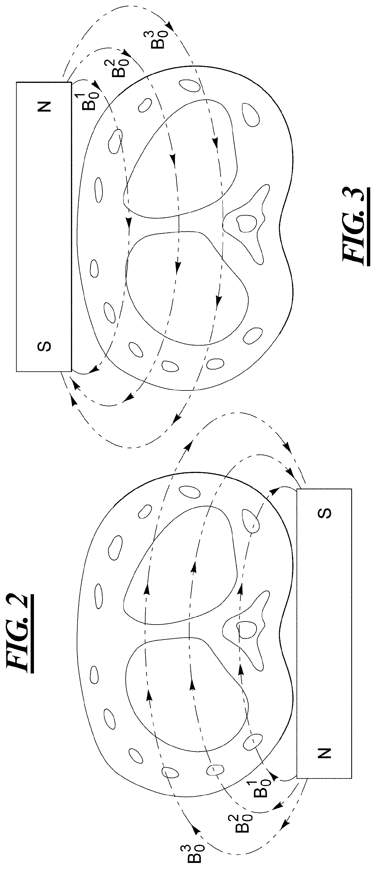
[0023]FIGS. 2 and 3 illustrate the basic concept of the MR scanner according to the invention, by showing the basic field magnet in respective positions above and below a cross-section of a patient's torso. The basic field magnet can be a permanent magnet, but is preferably an electromagnet, so that the polarity thereof can be selectively changed, as is the case between FIG. 2 and FIG. 3.

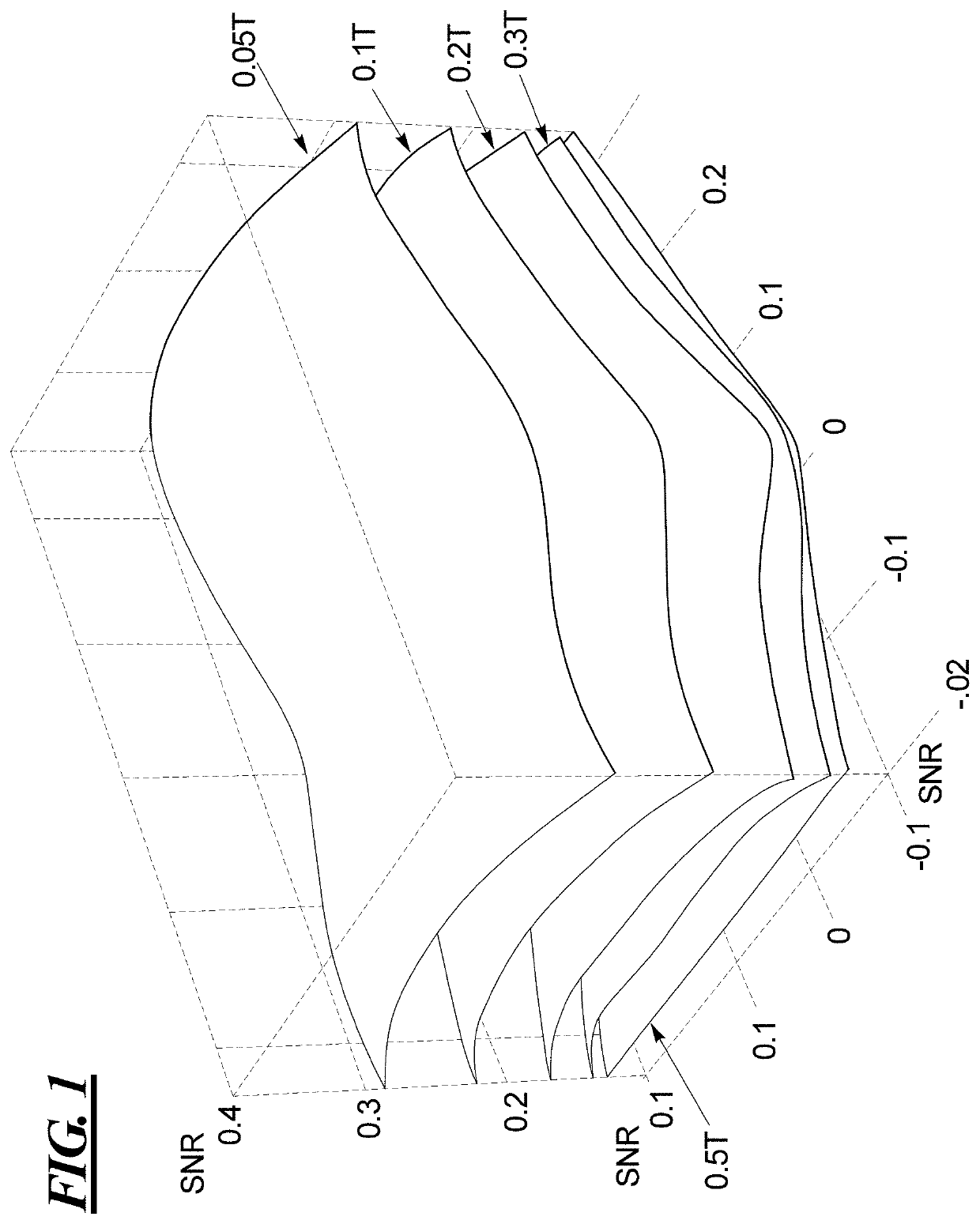
[0024]As can be seen in FIGS. 2 and 3, the basic field magnet produces a basic magnetic field in the torso, with field strengths at the respective fields lines designated as B03, B02 and B01. These different field strengths respectively result in MR signals being acquired with different SNRs, with the SNR for B01 being highest and the SNR for B03 being lowest, because the field strengths decrease with increasing distance from the basic field magnet.

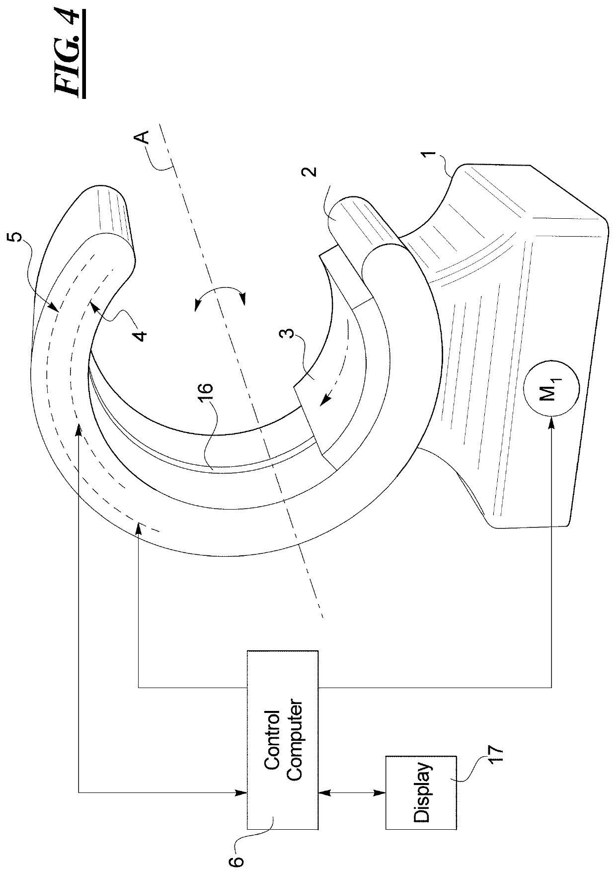
[0025]FIG. 4 is a perspective view of the basic components of an MR scanner according to the present invention. The MR scanner itself has a base 1, on wh...


PUM


Abstract

A magnetic resonance scanner has a base, a C-arm mounted on said base, the C-arm having an inner surface curved in a C-shape, the C-shape defining a plane, a magnet mounted on said inner curved surface of said C-arm, the magnet generating a basic magnetic field for magnetic resonance imaging, and a drive mechanism mechanically connected to the magnet. The drive mechanism rotates the magnet around an axis that is orthogonal to said plane so as to selectively position said magnet in at least two magnet positions that are respectively above and beneath a patient, who is situated in the C-arm along or parallel to the axis.

Description

BACKGROUND OF THE INVENTIONField of the Invention[0001]The present invention concerns methods and apparatuses for magnetic resonance imaging (MRI), and in particular concerns a method and an MR data acquisition scanner of the type known as an “open” system.Description of the Prior Art[0002]Magnetic resonance imaging (MRI) is a known modality for obtaining an image of the interior of an examination object. MRI has become a commonly used imaging modality in the field of medicine, wherein the examination object is a patient. An MR image has the advantage of being able to show anatomical details and physiological processes inside of the patient that often cannot be seen in images produced by other imaging modalities, such as conventional x-ray, computed tomography (CT) and ultrasound.[0003]In an MR system, the patient is moved into a device known as a scanner or imager, which has a patient-receiving space or volume therein, in which the patient must be placed in order to achieve the bes...

Claims


Application Information

Patent Timeline
Patent Type & Authority Applications(United States)
IPC IPC(8): G01R33/38G01R33/383G01R33/381G01R33/30
CPCG01R33/383G01R33/3806G01R33/3802G01R33/381G01R33/445G01R33/3808
Inventor POPESCU, STEFANVESTER, MARKUSSPEIER, PETERMÜLLER, EDGARCONSTABLE, ROBERT TODDGALIANA, GIGI
Owner YALE UNIV
Why Eureka
Try Eureka