Bipolar dc-dc converter topology using passive voltage reversal

Active Publication Date: 2020-10-01
THE BOARD OF TRUSTEES OF THE LELAND STANFORD JUNIOR UNIV
View PDF0 Cites 0 Cited by
  • Summary
  • Abstract
  • Description
  • Claims
  • Application Information

AI Technical Summary

Benefits of technology

This patent describes a power supply that can produce short pulses of electricity for various applications. The approach is efficient and can be used for both low and high voltage applications. It allows for the creation of smaller and lighter power supplies, reducing weight and cost. The design uses circulating currents to generate the necessary signals to control the pulse and polarity profiles of the load. The high switching frequency of the design allows for fast and precise operation without the need for complex drive circuits. The discharge circuit has a fast transient response, which allows for a long pulse width. The design also reduces the risk of arcing and contamination during electroporation. The invention can be scaled up in voltage without increasing the device ratings.

Problems solved by technology

Many systems use mono-polar pulses for simplicity but electro-migration can limit electrode life.
Conventional approaches for providing DC electrical pulses can be undesirably complicated, especially in cases (e.g., electroporation applications) where the pulses need to be bi-polar and / or need to have flexible pulse profiles.
Conventional methods can present difficulties including slow startup, large energy storage within the circuit, voltage droop, limited pulse repetition, and limited pulse width.
Gating can also become complicated for multilevel approaches with floating active switches.

Method used


Image

  • Bipolar dc-dc converter topology using passive voltage reversal
  • Bipolar dc-dc converter topology using passive voltage reversal
  • Bipolar dc-dc converter topology using passive voltage reversal

Examples


Embodiment Construction

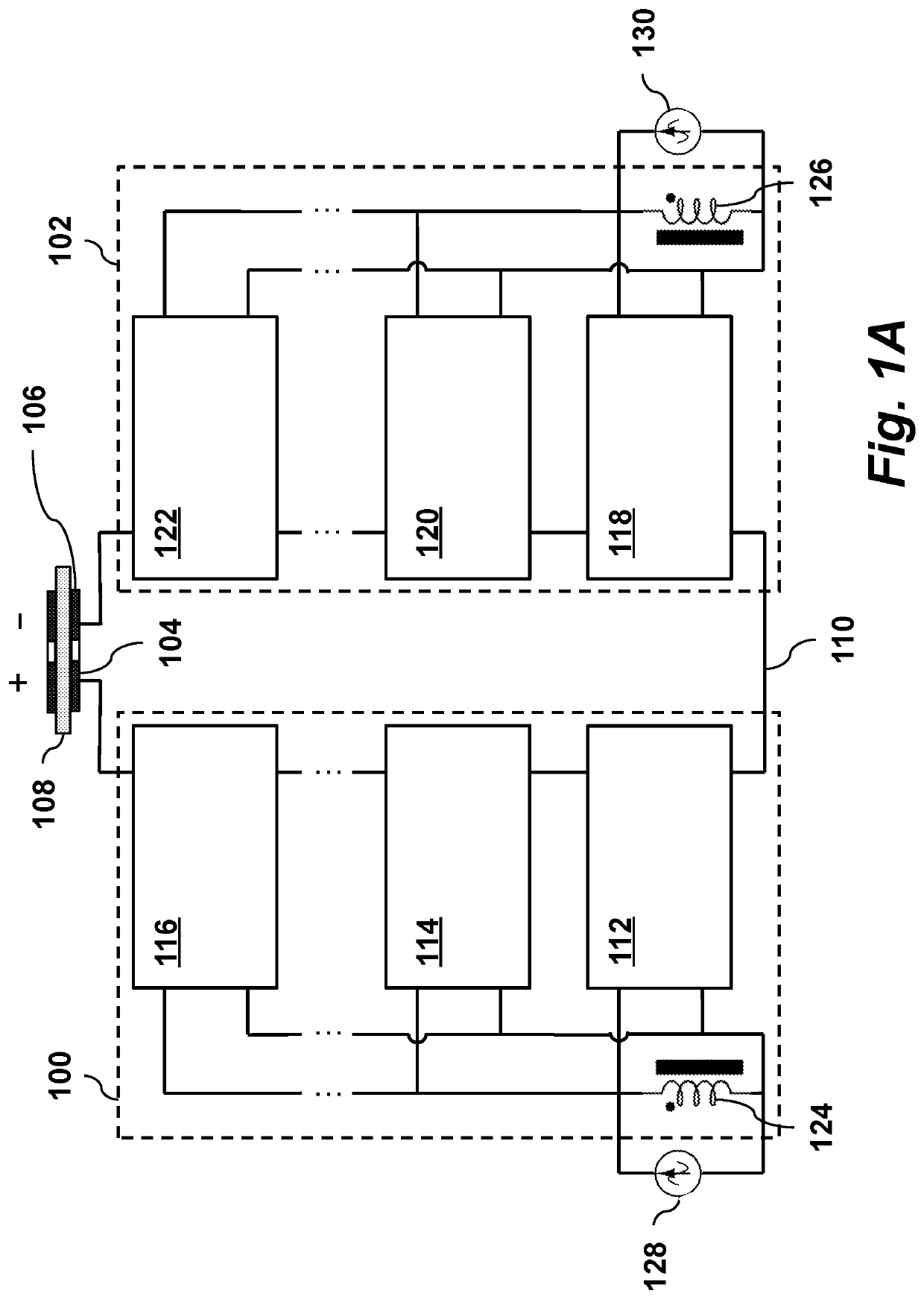
[0021]FIG. 1A depicts the general structure of the resonant rectifier schematic developed to generate the bipolar pulses for electroporation, according to one embodiment of the invention.

[0022]The circuit includes two opposing multi-level isolated rectifiers, left multi-level resonant rectifier bank 100 and right multi-level resonant rectifier bank 102. These are connected to positive and negative electrodes 104 and 106, respectively. For purposes of illustration, the load 108 contacting the electrodes in this figure is a treated liquid for electroporation. The low level of the rectifier banks are tied together to a common node 110. When the left side rectifier is active, the load will experience a positive voltage and when the right side is active the load will experience a negative voltage.

[0023]Through capacitive isolation, each rectifier bank may have multiple stages to achieve impedance matching and voltage gain. As shown, left rectifier bank 100 has multiple resonant rectifier...


PUM


Abstract

A resonant DC-DC converter for generating high voltage MHz bi-polar DC pulses includes a left multi-level resonant rectifier bank [100] connected to a positive electrode [104] and coupled via capacitive isolation to a left RF amplifier terminal [128]; a right multi-level resonant rectifier bank [102] connected to a negative electrode [106] and coupled via capacitive isolation to a right RF amplifier terminal [130]. Each multi-level resonant rectifier bank comprises multiple resonant rectifier stages [112-122], where each stage comprises two capacitors for capacitively isolating the stage, an output capacitor, a MOSFET switch connected to an adjacent MOSFET switch of an adjacent stage, and a gating resonant circuit connected to the MOSFET switch, whereby MOSFET switches in the banks can be passively controlled by RF signals from a left RF amplifier and a right RF amplifier.

Description

FIELD OF THE INVENTION[0001]The present invention relates generally to resonant DC-DC converters. More specifically, it relates to circuits for generating high voltage DC pulses using resonant rectifiers.BACKGROUND OF THE INVENTION[0002]Electroporation is a technique that uses high pulsed electric fields to create pores in biological cell walls for medical, liquid sterilization and other applications. Many systems use mono-polar pulses for simplicity but electro-migration can limit electrode life.[0003]Electroporation involves generating a large electric field between two conductive electrodes within a liquid. Biological cells exposed to the electric field develop pores in their cell walls. Reversible electroporation involves electric fields in the range of hundreds of volts per mm and can be used to move materials in and out of the cell. Irreversible electroporation, or pulse electric field (PEF) sterilization involves even higher electric fields and is used to usually destroy cell...

Claims


Application Information

Patent Timeline
IPC IPC(8): H02M3/335H02M1/08
CPCH02M3/33576H02M1/08H02M3/24H02M7/49H02M1/083H03K17/691Y02B70/10H02M1/0058H02M3/003
Inventor RAYMOND, LUKE C.LIANG, WEISURAKITBOVORN, KAWINRIVAS DAVILA, JUAN M.
Owner THE BOARD OF TRUSTEES OF THE LELAND STANFORD JUNIOR UNIV
Why Eureka
Try Eureka