
Method and device for operating an electric machine for outputting a predefined torque and a predefined rotational speed

a technology of electric machines and torques, applied in the direction of motor control for high speed, electric propulsion mounting, transportation and packaging, etc., can solve the problems of significantly lower restriction, increase in electrical losses in inverters and electric machines, etc., to reduce the stator flux, increase the maximum efficiency and torque of the machine, the effect of reducing the flux of magnetic stators

Active Publication Date: 2020-10-01
ROBERT BOSCH GMBH
View PDF2 Cites 2 Cited by
  • Summary
  • Abstract
  • Description
  • Claims
  • Application Information

AI Technical Summary

Benefits of technology

This patent is about a method and device for reducing the magnetic stator flux of an electric machine. This can be done to prevent demagnetization of the magnets in the machine, which can occur when the machine is operated at high temperatures or when the torque and speed are increased. The method involves using a field weakening controller or increasing the negative d-current to vary the stator flux and thereby control the torque and efficiency of the machine. Additionally, the patent also mentions that the level of stator flux can be adjusted based on the detected temperature to protect the magnets from damage. This technology is important for preventing demagnetization and ensuring the reliable operation of electric machines in high-temperature and high-torque settings.

Problems solved by technology

Ideally, the actual values during operation or during the control correspond to the predetermined values; a minimum deviation possibly occurs due to limited control accuracy of the controller used.
In particular, during the operation in the second operating mode, increased electrical losses are established in the inverter and the electric machine.
However, in the approach described here, this restriction is significantly lower than the torque limitation, for example by 30%, purely subject to the temperature.

Method used


Image

  • Method and device for operating an electric machine for outputting a predefined torque and a predefined rotational speed
  • Method and device for operating an electric machine for outputting a predefined torque and a predefined rotational speed

Examples


Embodiment Construction

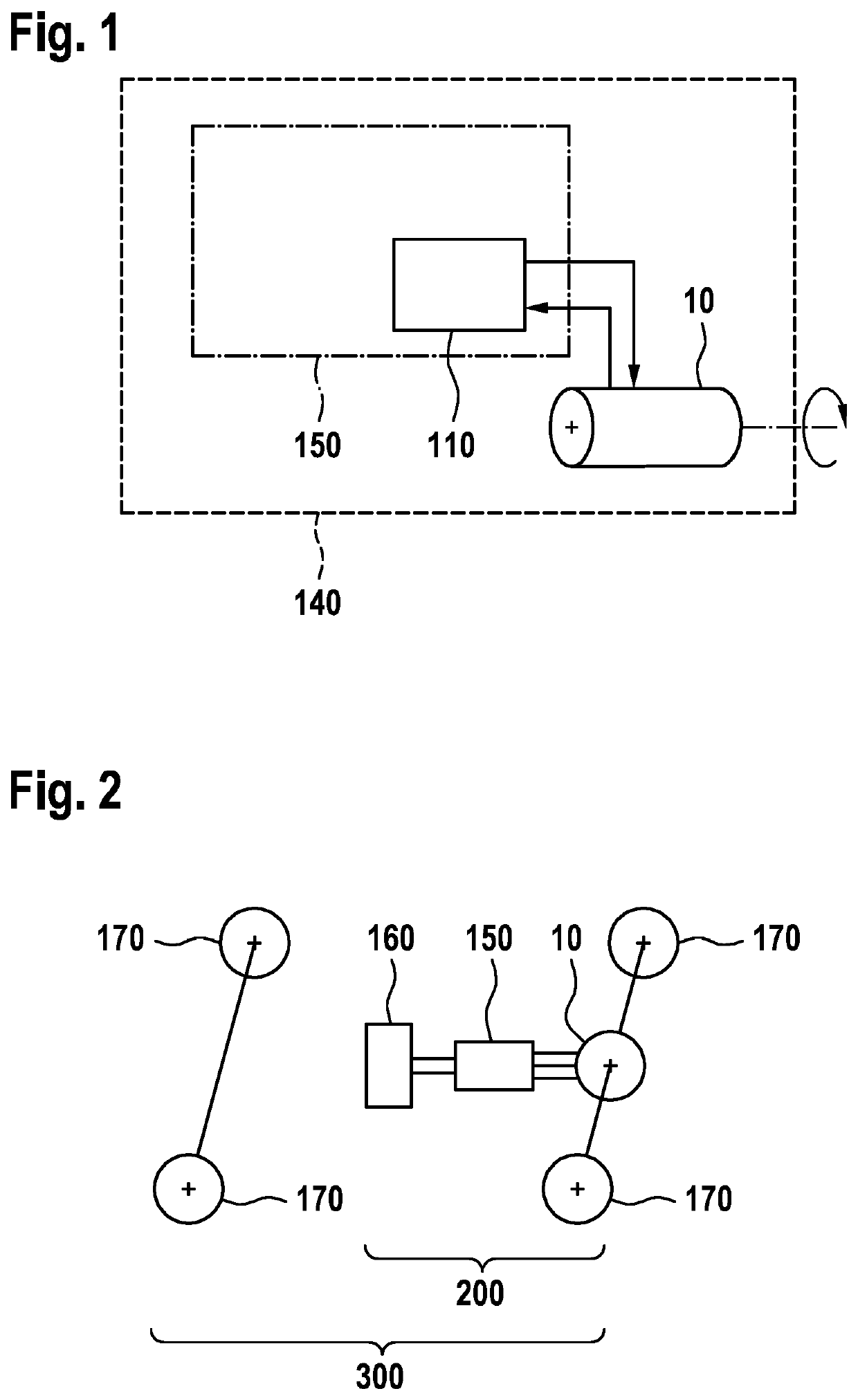
[0030]FIG. 1 shows a device 140, which comprises a control unit 150 and a logic unit 110 for operating an electric machine 10. The logic unit 110 operates or controls the electric machine 10 subject to a detected temperature of the electric machine 10. The logic unit 110 can be arranged separately from the electric machine 10, for example in a control device 150 or in an inverter. The logic unit 110, the control device 150 and / or the electric machine 10 can further be arranged together within a housing or within a device 140.

[0031]FIG. 2 shows a schematically illustrated vehicle 300 having a drive train 200. By way of example, the illustration shows a vehicle having four wheels 170, wherein the invention can equally be used in any vehicle having any number of wheels on land, on water and in the air. By way of example, the drive train 200 comprises a battery 160 for supplying the electric machine 10 of the drive train 200. The drive train further preferably comprises a control device...


PUM


Abstract

The invention relates to a method and device for operating an electric machine (10) for outputting a predefined torque and a predefined rotational speed, comprising the following steps: providing (420) a first and a second operating mode for the operation of the electric machine (10); detecting (430) a temperature of the electric machine (10); and operating the electric machine (10) in the first operating mode (440) if the detected temperature falls below a threshold value, and operating the electric machine (10) in the second operating mode (450) if the detected temperature corresponds with the threshold value or exceeds same. During the operation of the electric machine (10) in the second operating mode (450), with the resulting output of the predefined torque and the predefined rotational speed, the magnetic stator flux of the electric machine (10) is reduced compared with the magnetic stator flux of the electric machine (10) during the operation of the electric machine (10) in the first operating mode (440), with the resulting output of the predefined torque and the predefined rotational speed.

Description

BACKGROUND OF THE INVENTION[0001]The invention relates to a method and a device for operating an electric machine for outputting a predetermined torque and a predetermined rotational speed. The invention furthermore relates to a logic unit, a drive train having a corresponding logic unit and a vehicle having a corresponding drive train and a computer program and a machine-readable storage medium.[0002]An electric drive, in particular an electric machine, heats up during operation. To enable an electric machine to output a torque and rotate, magnets are incorporated in an electric machine, in particular in the rotor. The material properties of magnets are temperature-dependent. The greater the temperature of the magnets, the smaller the permissible opposing magnetic field load. If the permissible opposing magnetic field load is exceeded by an applied opposing magnetic field, the magnets demagnetize irreversibly. With at least partially demagnetized magnets, an electric machine no lon...

Claims


Application Information

Patent Timeline
Patent Type & Authority Applications(United States)
IPC IPC(8): H02P29/66H02P23/00B60K1/00
CPCH02P23/009H02P29/662B60K1/00H02P21/0089H02P29/60Y02T10/64
Inventor ROSEN, ALEXANDERBANGERTER, MICHAEL
Owner ROBERT BOSCH GMBH
Learn More