Simple Rotary Steerable Drilling System

a rotary steerable and drilling system technology, applied in the direction of directional drilling, borehole/well accessories, survey, etc., can solve the problems of borehole deviation, laborious process, and control of the direction in which the drill string deviates, and achieve the effect of reducing the fluid flow ra

Active Publication Date: 2020-10-08
GRAY
View PDF0 Cites 3 Cited by
  • Summary
  • Abstract
  • Description
  • Claims
  • Application Information

AI Technical Summary

Benefits of technology

[0044]The main advantages of the invention are its simplicity, the ability to drill at an angular build rate that is adjustable down hole by drilling fluid flow rate, the fact that the drill string rotates

Problems solved by technology

Initially, drillers found that by putting weight on the drill bit they could cause the borehole to deviate.
Although this technique worked, the problem was controlling the direction in which the drill string would deviate the path of the borehole.
This is a laborious process and is really suitable only for cases where a branch off the main borehole must be drilled, rather than for continuous directional control.
Rotating such an assembly in a near horizontal borehole generally leads to the hole drooping under the effects of gravity on the drill string and bit so that directional control is either reduced or lost.
Drilling while sliding the non-rotating drill string further into the borehole has significant limitations.
The first of these is that cuttings will build up within any borehole of adequately flat trajectory causing increased friction.
With intermediate borehole angles, the cuttings bed may suddenly dislodge causing a hole blockage which can t

Method used


Image

  • Simple Rotary Steerable Drilling System
  • Simple Rotary Steerable Drilling System
  • Simple Rotary Steerable Drilling System

Examples


Embodiment Construction

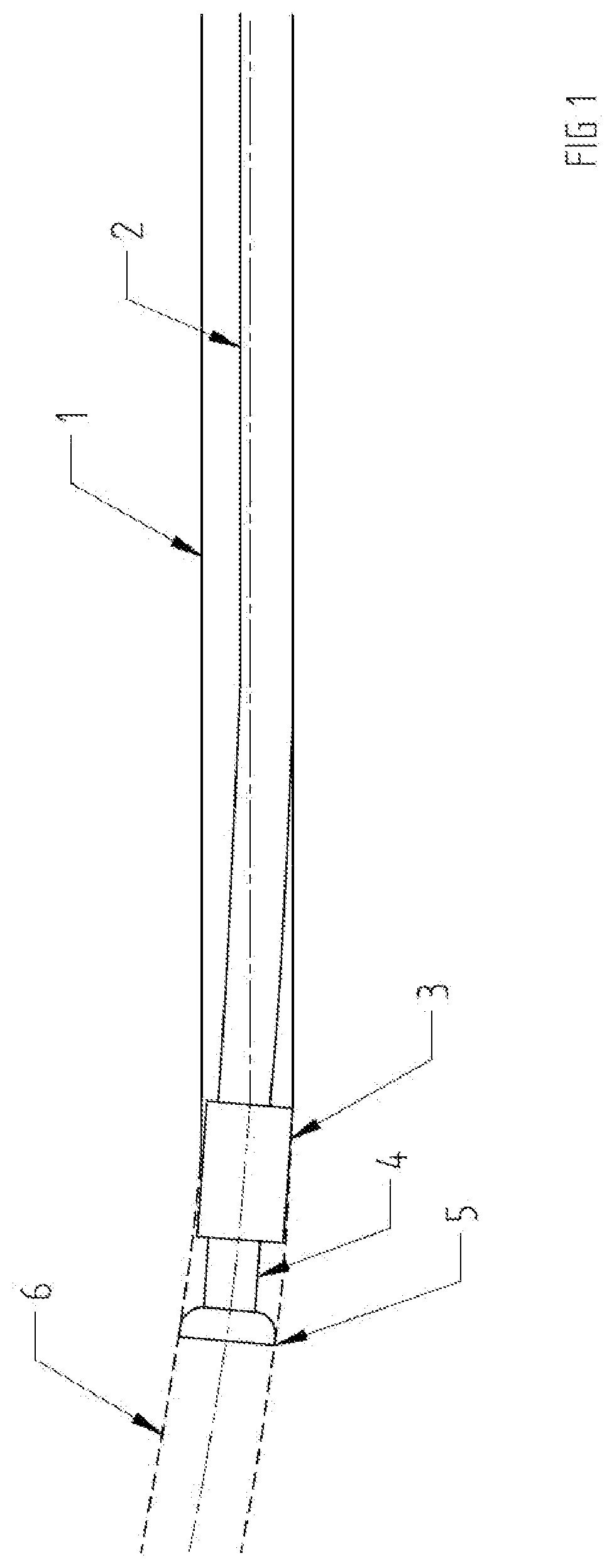
[0054]FIG. 1 illustrates a horizontal borehole (1) in which a drill string (2) lies on the bottom thereof until deflected by the steering collar (3). The steering collar (3) enables the transmission of the rotating motion of the drill string from its right hand side (as shown) to an extended part of the drill string (4) on its left hand side, and then to the drill bit (5) itself. Because the steering collar (3) laterally deflects the drill string (4) and the bit (5), the latter cuts a deviated path and will continue to do so in the desired path (6). In this form, the steering collar (3) is being used to push the bit (5) sideways to effect a directional change of the borehole (1). It should be appreciated that the steering collar (3) may be used in this mode to push in any lateral direction in the borehole (1) to change the alignment of the borehole (1).

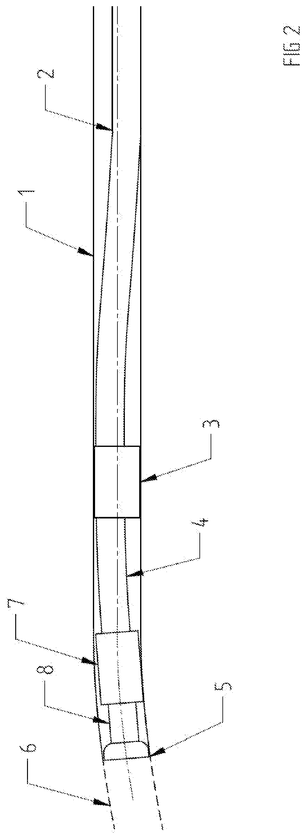
[0055]FIG. 2 illustrates the borehole (1) in which the drill string (2) lies on the bottom of the borehole (1) in the right side of ...


PUM


Abstract

A steering collar for deflecting a drill string in a borehole to cause the borehole to be drilled in a different direction. The steering collar surrounds a hollow drive shaft which is driven by the drill string. During normal drilling operations, the steering collar does not rotate with the drive shaft. The steering collar has three sets of pistons operated by the pressure of the drilling fluid, one set of which is pressure relieved. Drill fluid that is pumped down the drill string flows into the hollow drive shaft and through ports to activate the pistons which thereby force corresponding pads outwardly into contact with the sidewall of the borehole. Since the one set of pistons is pressure relieved, it does not force its pad against the borehole sidewall with as much pressure as the other two sets of pistons force their pads against the sidewall of the borehole. Accordingly, the steering collar is deflected laterally in the borehole so that the drill bit is also steered laterally to cause drilling in a different direction. In order to reorient the steering collar in the borehole, the steering collar can be locked to the drive shaft so that when the drill string is rotated, the steering collar is also rotated so that it is moved to a new angular position in the borehole.

Description

TECHNICAL FIELD OF THE INVENTION[0001]The invention relates to the field of directionally controlled drilling of boreholes.BACKGROUND OF THE INVENTION[0002]Any discussion of the prior art throughout the specification should in no way be considered as an admission that such prior art is widely known or forms part of common general knowledge in the field.[0003]The drilling of a borehole in a controlled direction has evolved to more efficiently reach deposits of hydrocarbon materials. Rather than drilling a borehole downwardly to access underlying deposits of gas and oil, with the advent of directional drilling a borehole can be drilled downwardly at a convenient location on the surface and then laterally to a remote location where the hydrocarbon deposit is located. Initially, drillers found that by putting weight on the drill bit they could cause the borehole to deviate. The placement of centralisers on the drill string could be used to control the rate at which such deviation would ...

Claims


Application Information

Patent Timeline
IPC IPC(8): E21B7/06
CPCE21B7/062E21B17/1014E21B47/024E21B7/068E21B7/067E21B3/00
Inventor GRAY
Owner GRAY
Why Eureka
Try Eureka