Hollow fiber membrane module and module arrangement group thereof

a technology of hollow fiber membrane and module, applied in the field of can solve the problems of increasing the piping space and cost of parts other than hollow fiber membrane modules, difficult to effectively use supply pressure, and high cost and piping space, so as to prolong the membrane life, reduce the frequency of exchanging hollow fiber membrane elements, and reduce the effect of pressure drop

Inactive Publication Date: 2006-07-06
TOYO TOYOBO CO LTD
View PDF8 Cites 31 Cited by
  • Summary
  • Abstract
  • Description
  • Claims
  • Application Information

AI Technical Summary

Benefits of technology

[0041] Examples of permselective hollow fiber membranes for use in the present invention include gas separation membranes, microfiltration membranes, nanofiltration membranes, reverse osmosis membranes, etc. In particular, the present invention can be effectively applied to a reverse osmosis hollow fiber membrane module for seawater desalination or like purposes.
[0042] Reverse osmosis membranes usable in the present invention are separation membranes capable of separating substances with a molecular weight of several tens of daltons, and specifically, those capable of removing at least 90% of the salt at an operation pressure of 0.5 MPa or more. When hollow fiber reverse osmosis membranes are used for seawater desalination, they preferably have a structure that makes it unlikely to cause clogging with turbidity components, since seawater, the fluid to be treated, contains a large proportion of turbidity components. Therefore, the present invention advantageously achieves its effects when applied to seawater desalination.
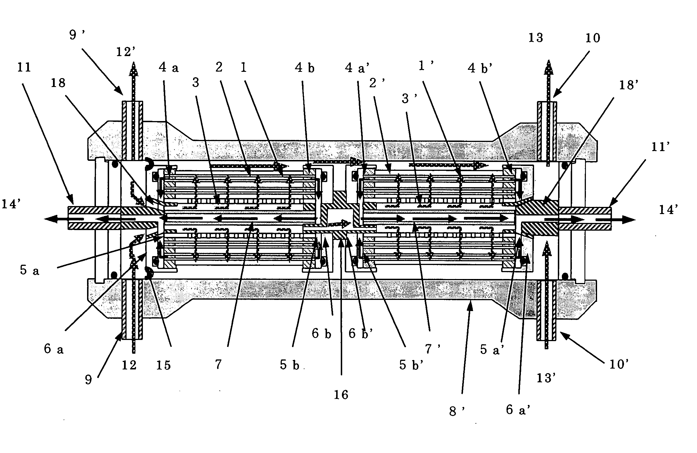
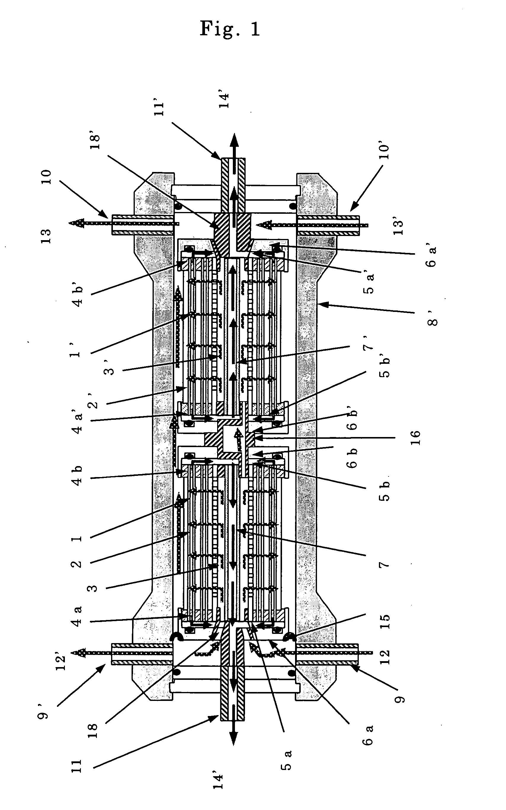
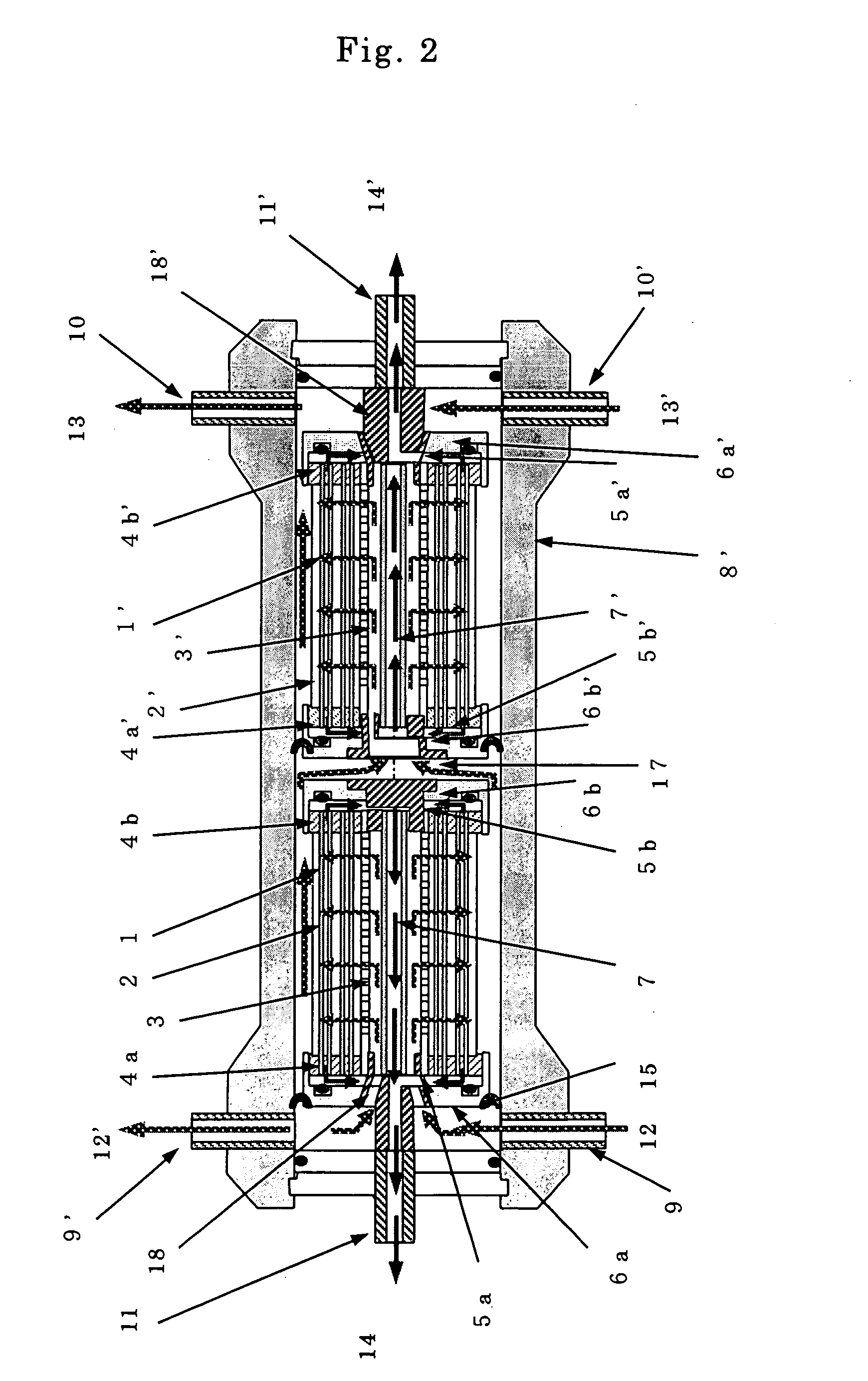
[0043] In the present invention, a hollow fiber membrane assembly comprising permselective hollow fiber membranes arranged in a crisscross fashion around the feed fluid distribution pipe, means an assembly in which hollow fiber membranes are arranged to cross each other with a winding angle with respect to the axial direction of the feed fluid distribution pipe. For example, such an assembly can be produced by rotating the feed fluid distribution pipe to wind a hollow fiber membrane or a bundle of two or more hollow fiber membranes while causing the membrane or bundle to traverse in the axial direction of the feed fluid distribution pipe. The hollow fiber membranes, when arranged in a crisscross fashion, are in point-contact with each other and thus have spaces therebetween, making it easy for the feed fluid to be distributed evenly through the whole hollow fiber membrane assembly. Therefore, such an arrangement suppresses the pressure drop caused when the feed fluid passes between the hollow fiber membranes, and thus inhibits drifting in the hollow fiber membrane layers. Further, the adsorption and/or deposition of turbidity components in the feed fluid on the hollow fiber membrane surfaces occurs evenly in the whole assembly, resulting in prolonged membrane life, i.e., reduction in the frequency of exchanging the hollow fiber membrane element, and other cost-cutting effects.
[0044] In a preferable embodiment of the present invention, two or more hollow fiber membrane elements are installed in one pressure vessel. This reduces the pressure vessel cost per hollow fiber membrane element, and also reduces the piping for connecting hollow fiber membrane modules, thereby decreasing the space per hollow fiber membrane element.
[0045] When the operation is performed under such conditions as to set the recovery rate, i.e., the proportion of the permeated fluid flow rate to the feed fluid flow rate, low, or when a small pressure drop in the hollow fiber membrane module is desired,

Problems solved by technology

Therefore, in the status quo, hollow fiber membrane module arrangement groups need to have a large number of high pressure pipes and headers of such pipes, and thus require high cost and a large space for piping.
Especially in hollow fiber membrane modules for seawater desalination, since such modules are generally operated at a high pressure of 6 MPa or more, feed liquid pipes, concentrated liquid pipes and the headers of such pipes are designed to have high pressure resistance, increasing the piping space and cost of parts other than the hollow fiber membrane modules.
Generally, six spiral wound reverse osmosis membrane elements are installed, and in such a case, the pressure drop of the module is large, making it difficult to effe

Method used


Image

  • Hollow fiber membrane module and module arrangement group thereof
  • Hollow fiber membrane module and module arrangement group thereof
  • Hollow fiber membrane module and module arrangement group thereof

Examples


example 1

(Production of Hollow Fiber Membranes)

[0098] Forty parts by weight of cellulose triacetate (acetylation degree: 61.4) was mixed with a solution composed of 18 parts by weight of ethylene glycol and 42 parts by weight of N-methyl-2-pyrrolidone, and the mixture was heated to obtain a solution for forming membranes. The solution was degassed under reduced pressure, and then discharged from a nozzle to travel through the air into a coagulating liquid composed of 65 parts by weight of water at 14° C., 10.5 parts by weight of ethylene glycol and 24.5 parts by weight of N-methyl-2-pyrrolidone, to thereby form hollow fibers. Subsequently, the hollow fiber membranes were washed with water at normal temperature to remove excessive solvent and nonsolvent, and then treated with hot water. Thus, hollow fiber reverse osmosis membranes made of cellulose triacetate membranes were produced.

[0099] The obtained hollow fiber membranes had an outer diameter of 137 μm and an inner diameter of 53 μm. T...

example 2

[0102] A hollow fiber membrane module arrangement group as shown in FIG. 4 was formed from six hollow fiber membrane modules produced in the same manner as in Example 1. Feed fluid pipe portions and concentrated fluid pipe portions that were designed for use under high pressures were limited to the portions for connecting the hollow fiber membrane modules. Since high pressure-pipes were used only for the connecting portions, the lengths of such pipes were 0.5 m for the feed fluid, and 0.5 m for the concentrated fluid. Neither header pipes nor branch pipes were necessary.


PUM


Abstract

The present invention provides a hollow fiber membrane module comprising hollow fiber membrane element or elements in a pressure vessel, in which a feed fluid can be supplied to a feed fluid distribution pipe disposed at a center portion of each hollow fiber membrane element, the pressure vessel having at least two feed fluid passage nozzles on the outer peripheral side in the vicinity of one end and at least two concentrated fluid passage nozzles on the outer peripheral side in the vicinity of the other end; and a hollow fiber membrane module arrangement group that comprises such hollow fiber membrane modules and substantially eliminates need for header pipes at the supply side and the concentration side.

Description

TECHNICAL FIELD [0001] The present invention relates to a hollow fiber membrane module comprising permselective hollow fiber membranes. The present invention relates to a hollow fiber membrane module comprising permselective hollow fiber membranes, the module being applicable for membrane separation treatments of fluids, such as, for example, the desalination of seawater, desalination of brine, purification of wastewater, production of sterile water, production of ultrapure water, and like reverse osmosis processes; advanced water purification treatment, removal of low-molecular-weight toxic substances such as agricultural chemicals, odorants and disinfection by-product precursors, water softening treatment by removal of hardness components, and like nanofiltration processes; recovery of paint from electrocoating wastewater, concentration and / or recovery of useful food-related materials, water purification treatment substituting for coagulation sedimentation and / or sand filtration, ...

Claims


Application Information

Patent Timeline
IPC IPC(8): B01D63/04B01D61/02B01D63/02B01D65/00C02F1/44
CPCB01D61/022B01D63/02B01D63/043B01D65/00C02F1/441C02F2103/08B01D2313/10B01D2313/20Y02A20/131B01D61/026
Inventor KUMANO, ATSUOMARUI, KATSUSHIGEKOTERA, HIDETOFUJIWARA, NOBUYA
Owner TOYO TOYOBO CO LTD
Why Eureka
Try Eureka