
Independent control of etching and passivation gas components for highly selective silicon oxide/silicon nitride etching

a technology of silicon oxide and passivation gas, which is applied in the direction of semiconductor/solid-state device manufacturing, basic electric elements, electric devices, etc., can solve the problems of lack of separate control of the etching component fluorine or hydrogen) versus the passivation component (e.g., carbon) in the plasma-excited processing field, and the challenge of semiconductor technology developmen

Active Publication Date: 2020-10-08
TOKYO ELECTRON LTD
View PDF0 Cites 3 Cited by
  • Summary
  • Abstract
  • Description
  • Claims
  • Application Information

AI Technical Summary

Benefits of technology

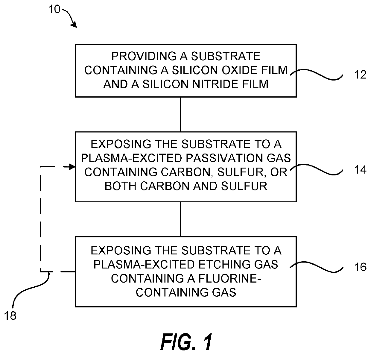
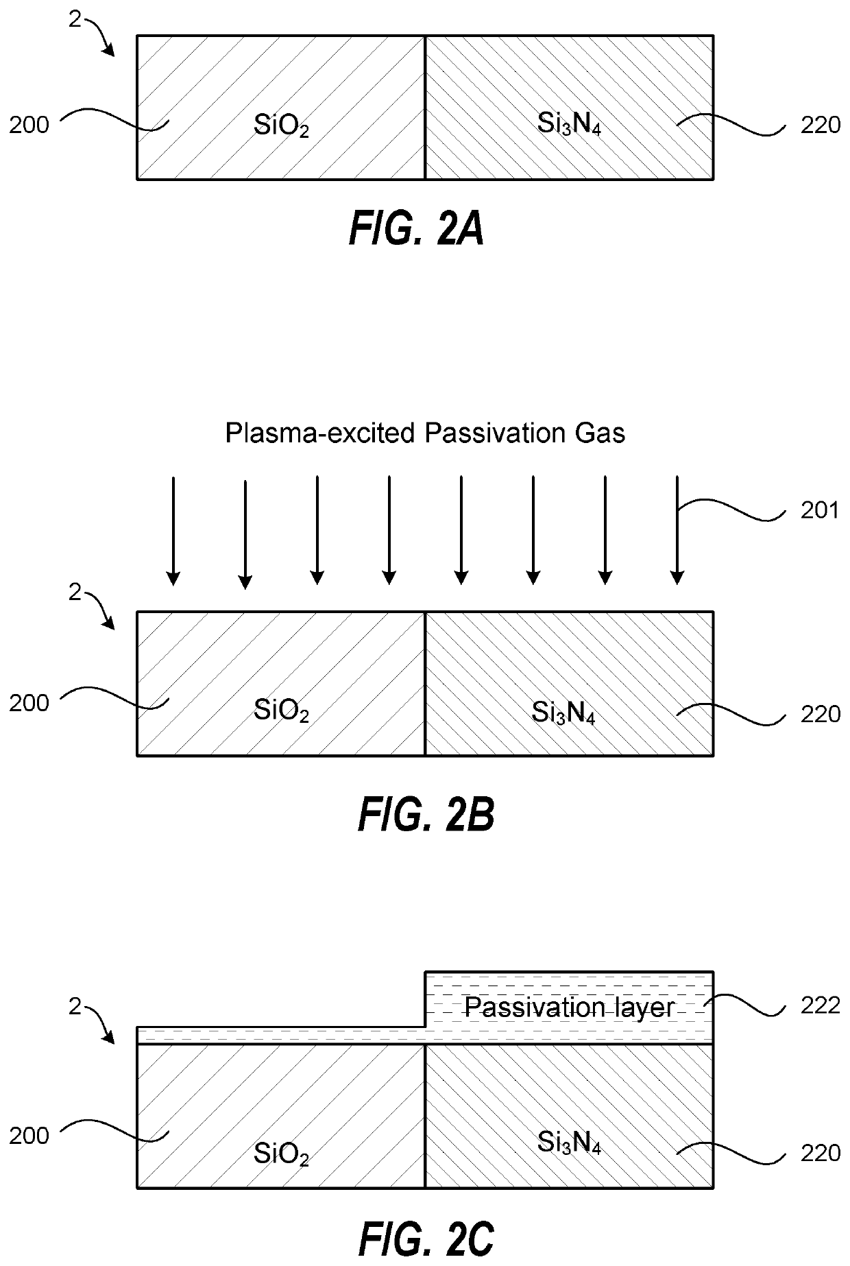
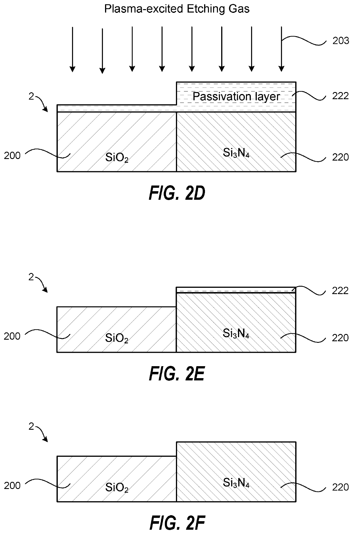
The patent text describes a method of selectively etching silicon oxide relative to silicon nitride in semiconductor manufacturing. The method involves exposing the substrate to a plasma-excited passivation gas containing carbon, sulfur, or both, followed by a plasma-excited etching gas containing fluorine or a combination of fluorine and another gas. The method can selectively remove silicon oxide while preserving silicon nitride, which can be useful in semiconductor manufacturing processes where both materials are present.

Problems solved by technology

Next generation semiconductor technology development poses a huge challenge as dry etch removal of one material selective to other materials is needed.
However, many conventional etching methods have limitations that include lack of separate control of the etching component fluorine or hydrogen) versus the passivation component (e.g., carbon) in the plasma-excited processing gas.
Further, many etching methods use only one FC or HFC gas, which provides inadequate flexibility for selectively etching silicon oxide relative to silicon nitride for advanced semiconductor devices.
Attempts to fully separate the etching component and the passivation component have not provided full independent control.

Method used


Image

  • Independent control of etching and passivation gas components for highly selective silicon oxide/silicon nitride etching
  • Independent control of etching and passivation gas components for highly selective silicon oxide/silicon nitride etching
  • Independent control of etching and passivation gas components for highly selective silicon oxide/silicon nitride etching

Examples


Embodiment Construction

[0013]A method of selective plasma etching of silicon oxide relative to silicon nitride is described. The method utilizes independent control of etching and passivation gas components for highly selective silicon oxide / silicon nitride etching.

[0014]The inventive selective plasma etching of silicon oxide relative to silicon nitride described in embodiments of the invention fundamentally differs from conventional silicon oxide or silicon nitride etching process by plasmas containing a fluorocarbon (FC) gas or a hydrofluorocarbon (HFC) gas. In the inventive process, the passivation gas does not contain fluorine or hydrogen species that contribute to etching, but the passivation gas includes a passivation component (carbon, sulfur, or both carbon and sulfur) that shows sufficient volatility difference on silicon oxide versus silicon nitride. The higher volatility of the passivation component on silicon oxide surfaces is thought to be due to the “closed-shell” nature (no unpaired electro...


PUM


Abstract

A method for selective plasma etching of silicon oxide relative to silicon nitride is described. The method includes providing a substrate containing a silicon oxide film and a silicon nitride film, and selectively etching the silicon oxide film relative to the silicon nitride film by: a1) exposing the substrate to a plasma-excited passivation gas containing carbon, sulfur, or both carbon and sulfur, where the plasma-excited passivation gas does not contain fluorine or hydrogen, and b1) exposing the substrate to a plasma-excited etching gas containing a fluorine-containing gas. The method can further include, between a1) and b1), an additional step of a2) exposing the substrate to a plasma-excited additional passivation gas containing a fluorocarbon gas, hydrofluorocarbon gas, a hydrochlorocarbon gas, a hydrochlorofluorocarbon gas, or a hydrocarbon gas, or a combination thereof.

Description

CROSS-REFERENCE TO RELATED APPLICATIONS[0001]This application is related to and claims priority to U.S. Provisional Patent Application Ser. No. 62 / 830,223 filed on Apr. 5, 2019, the entire contents of which are herein incorporated by reference.FIELD OF INVENTION[0002]The present invention relates to the field of semiconductor manufacturing and semiconductor devices, and more particularly, to a method of selective plasma etching of silicon oxide relative to silicon nitride in semiconductor manufacturing.BACKGROUND OF THE INVENTION[0003]Next generation semiconductor technology development poses a huge challenge as dry etch removal of one material selective to other materials is needed. Selective silicon oxide etching relative to silicon nitride has many applications and preferential passivation (mostly carbon-based) has been extensively explored for high etch selectivity when using plasmas containing fluorocarbon (FC) or hydrofluorocarbon (HFC) gases. However, many conventional etchin...

Claims


Application Information

Patent Timeline
Patent Type & Authority Applications(United States)
IPC IPC(8): H01L21/3065
CPCH01L21/30655H01L21/31116H01L21/31144H01L21/02164H01L21/0217
Inventor ZHANG, DUTSAI, YU-HAOWANG, MINGMEI
Owner TOKYO ELECTRON LTD
Learn More