Pressure equalizing construction for nonporous acoustic membrane

Active Publication Date: 2020-10-15
WL GORE & ASSOC INC
View PDF0 Cites 5 Cited by
  • Summary
  • Abstract
  • Description
  • Claims
  • Application Information

AI Technical Summary

Benefits of technology

[0013]In embodiments, components (or layers) of a pressure equalizing assembly can introduce a decrease in acoustic sensitivity of an acoustic device assembled with the pressure equalizing assembly caused by absorption or redirection of acoustic energy, herein described as insertion losses. Insertion losses may be measured as a decrease in acoustic pressure (e.g. in dB) as measured by an acoustic transducer in a pressure equalizing assembly compared to a similarly situated transducer without any nonporous membrane or breathable layer. Preferably, embodiments will produce minimal insertion losses (i.e. no insertion losses or minor insertion losses) over a range of frequencies (i.e., a small insertion loss that is consistent in amplitude across a range of frequencies). Some embodiments may produce insertion losses that peak in amplitude at one or more frequencies or frequency ranges. In some embodiments, a pressure equalizing assembly c

Problems solved by technology

In particular, acoustic transducers (e.g. microphones) may be sensitive to fouling.
A continuing problem that exists is that many acoustic cover designs prove unsuitable for some environments.
For example, increasing the resiliency of a design against water penetration can decrease the ability of the

Method used


Image

  • Pressure equalizing construction for nonporous acoustic membrane
  • Pressure equalizing construction for nonporous acoustic membrane
  • Pressure equalizing construction for nonporous acoustic membrane

Examples


example 1

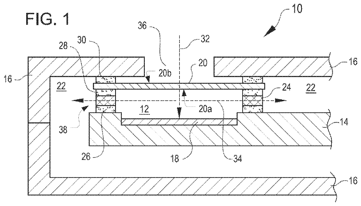
[0062]Assemblies similar to the arrangement of FIG. 1 were assembled to assess the venting rate of various additional breathable layer materials, as detailed below in Table 1. In airflow tests, the sample assemblies were reversed and clamped against an orifice of a steel plate, such that air could be passed through the orifice into the acoustic cavity. An ATEQ® Premier D Compact Flow Tester was used to measure airflow rate (mL / min) out of the acoustic cavity (i.e. through the breathable layers) by challenging it with 1 psi of air pressure through the orifice in the steel plate.

[0063]In pressure equilibration tests, each sample assembly was connected with a simulated microphone cavity containing a first pressure transducer, and attached (sealed) to the simulated microphone cavity at ambient pressure. The simulated microphone cavities and sample assemblies were inserted into a pressure vessel, along with second pressure transducers outside the simulated microphone cavities. The pressu...

example a

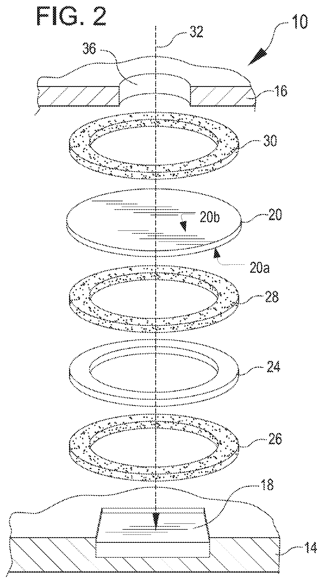
[0065]An acoustic protective cover assembly was constructed using five layers. The first layer was a ring of double-sided self-adhesive tape consisting of a PET backing and a tackified acrylic adhesive (TESA® 4972, 48 μm thick). The second layer was stacked on top of the first layer. The second layer was a continuous non-porous polymeric film. The third layer was stacked on top of the first and second layers. The third layer was a ring of double-sided self-adhesive tape consisting of a PET backing and a tackified acrylic adhesive (TESA® 4983, 30 μm thick). The fourth layer was stacked on top of the first three layers. The fourth layer was a ring of woven material (Milliken & Company, Part number 170357). The fifth layer was stacked on top of the first four layers. The fifth layer was a ring of double-sided self-adhesive tape consisting of a PET backing and a tackified acrylic adhesive (TESA® 4983, 30 μm thick). This assembly was tested for pressure equilibration, ATEQ airflow, and a...

example b

[0066]An acoustic protective cover was constructed of five layers as described in Example A. However, layer four of the sample was a polyester non-woven material (Hollytex®, Ahlstrom Corporation, Grade: 3254, 0.102 mm thick). This assembly was tested for pressure equilibration, ATEQ airflow, and acoustic insertion loss. The orientation of the sample was such that the fourth layer was closest to the pressure transducer, air pressure source, or microphone respectively. This sample had an adequate pressure equilibration time as evidenced by a 3.06 second exponential time constant. This sample also had an acceptable airflow rate of 22 mL / min and an acoustic response without the presence of an insertion loss peak.


PUM


Abstract

A pressure equalizing assembly with a nonporous membrane traversing across an acoustic pathway defined by an opening in a housing. A breathable layer connected to the nonporous membrane may be laterally arranged to the acoustic pathway. An acoustic cavity is defined by the breathable layer and nonporous membrane. The nonporous membrane has a side facing the opening in the housing to prevent fluid or moisture from penetrating into the acoustic cavity. The breathable layer further equalizes pressure in the acoustic cavity by providing a venting layer.

Description

PRIORITY CLAIM[0001]The present application claims the priority of U.S. Provisional App. No. 62 / 319,114, filed on Apr. 6, 2016, the entire contents and disclosures of which is hereby incorporated by reference.TECHNICAL FIELD[0002]The present disclosure relates generally to pressure equalizing constructions. More specifically, but not by way of limitation, this disclosure relates to a pressure-equalizing construction for protecting an acoustic device and equalizing pressure at the acoustic device.BACKGROUND OF THE INVENTION[0003]Acoustic cover technology is utilized in many applications and environments, for protecting sensitive components of acoustic devices from environmental conditions. Various components of an acoustic device operate best when not in contact with debris, water, or other contaminants from the external environment. In particular, acoustic transducers (e.g. microphones) may be sensitive to fouling. For these reasons, it is often necessary to enclose working parts of...

Claims


Application Information

Patent Timeline
IPC IPC(8): H04R1/02
CPCH04R1/02H04R19/005H04R19/04
Inventor KENALEY, RYANRINGQUIST, MICHAEL
Owner WL GORE & ASSOC INC
Why Eureka
Try Eureka