
Optical structural health monitoring

Pending Publication Date: 2020-10-29
TYSON II JOHN
View PDF1 Cites 8 Cited by
  • Summary
  • Abstract
  • Description
  • Claims
  • Application Information

AI Technical Summary

Benefits of technology

The invention is a technology for monitoring the health of structures, such as airplanes, by using an invisible paint or coating that doesn't hide or distract from the surface. This allows for earlier detection of issues and reduces maintenance costs, improves safety and performance, and extends the life of the structure. Additionally, data analytics and machine learning can be used to analyze the millions of images and data collected from Optical SHM of entire structures, providing more sensitivity and accuracy than human visual inspection.

Problems solved by technology

The cost of carrying out a D-Check on an aircraft is substantial, involving several million dollars for each D-Check, and the aircraft typically is our of service, as the D-Check usually will take about three to six weeks to complete.
A number of next generation aircraft are being made more of composite structures, which do not show their damage well visually.
They typically carry strain without noticeable changes until catastrophic failure, typically complete fracture, like a composite fishing rod that bends and bends until it snaps.
These tough, inflatable structures prevent micrometeorite penetration with an advanced woven composite structure, but the surface is damaged by the impact.

Method used


Image

  • Optical structural health monitoring
  • Optical structural health monitoring
  • Optical structural health monitoring

Examples


Embodiment Construction

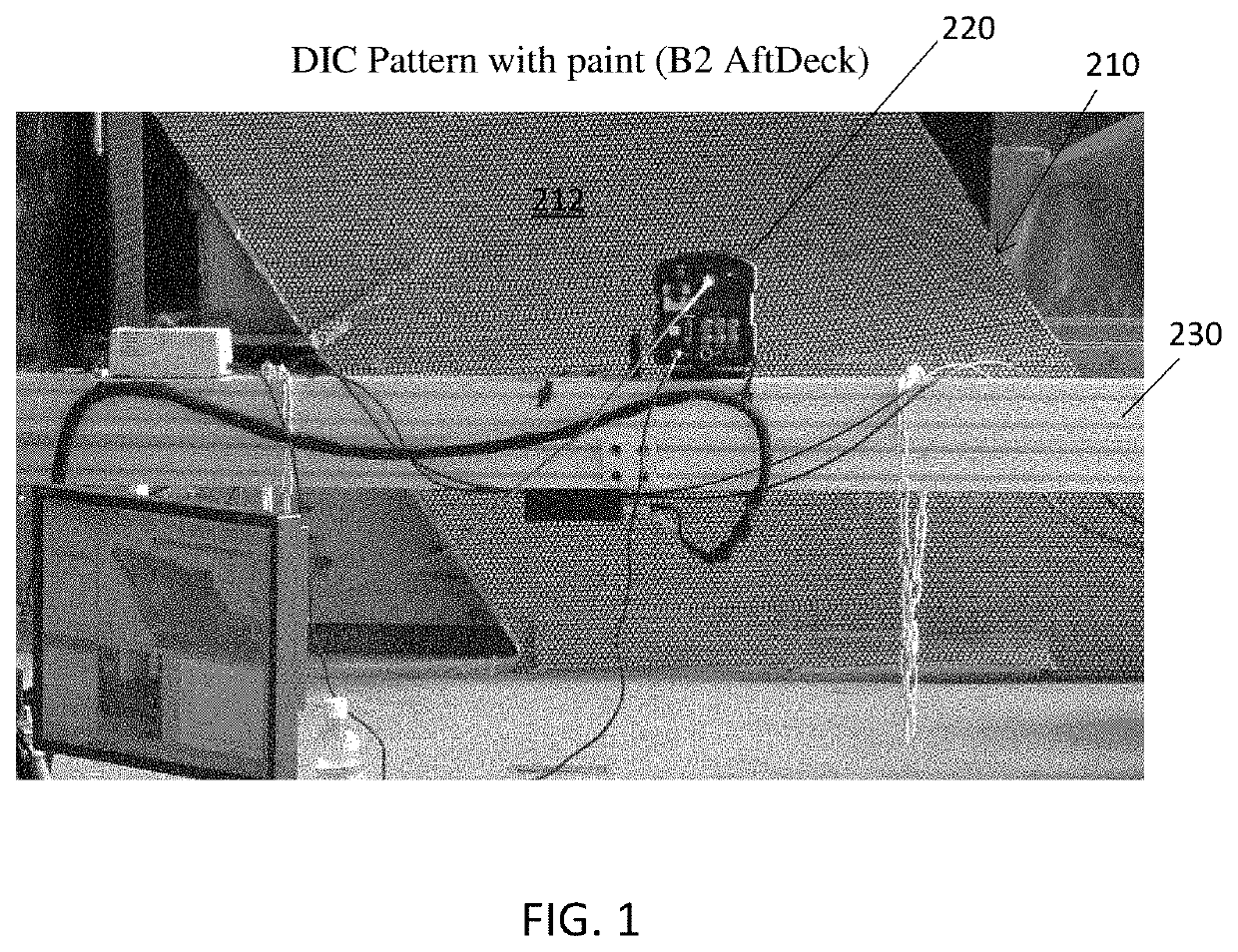
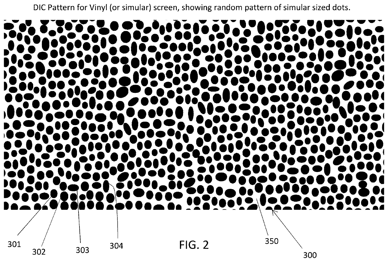
[0082]Referring to FIG. 1, there is depicted a panel 210 of an aircraft. The panel 210 is an aft deck panel of a B2 aircraft, located at the rear of the aircraft, which comprises a metallic panel on the bomber's upper surface that shields its composite airframe from the heat of engine exhaust. The panel 210 therefore is susceptible to a variety of conditions, including, for example, strain as well as heat. The aft deck panel 210 is shown having a pattern 211 on its outer surface 212. In this exemplary embodiment, the pattern is comprised of indicia that are dots. The panel 210 in FIG. 1 shows a preferred example of a dot pattern that has been applied to the panel surface 212. The pattern may be applied using a suitable application means, some examples of which may include painting, printing, and the like. According to a an exemplary embodiment, the pattern may be applied with a paint or ink. Preferably, the painted on pattern must remain on the panel for the duration of the testing ...


PUM


Abstract

Methods, systems and devices for optical structural health monitoring of a subject, including the utilization of pointillism to provide a design or painting of the surface of the structure to be monitored, which also serves as a mechanism for conducting SHM, implementing digital image correlation (DIC) by applying a pattern comprising a random dot pattern and / or codes. The subject is imaged using imaging equipment to capture images of the pattern. For some applications, the captured images of the pattern and codes are stored in a CAD file that represents the subject or portion thereof to which the pattern and codes are applied, and includes the locations of the pattern and codes. Indicia applied to a structure may be applied using a paintjet or inkjet, or robotic mechanism, while some applications implement pre-patterning of a composite sheet that is used to form the structure.

Description

CROSS-REFERENCE TO RELATED APPLICATIONS[0001]This application is a continuation-in-part of U.S. patent application Ser. No. 16 / 236,081, filed on Dec. 28, 2018, and of U.S. patent application Ser. No. 16 / 236,072, filed on Dec. 28, 2018, and claims the benefit to U.S. Provisional Application 62 / 750,012, filed on Oct. 24, 2018, and U.S. Provisional Application 62 / 612,181, filed on Dec. 29, 2017; the entire contents of the aforementioned applications of which are incorporated herein by reference.BACKGROUND OF THE INVENTION1. Field of the Invention[0002]The present invention relates to the field of inspection and monitoring of structures and components, and in particular to methods, systems and devices for measuring strain and deformities that may exist in a structure or object, including those occurring over time.2. Brief Description of the Related Art[0003]Components and structures that are in use and subjected to forces typically are monitored to determine whether changes have taken p...

Claims


Application Information

Patent Timeline
IPC IPC(8): G01B11/16G01J5/00B25J19/02B25J15/00B64C39/02G06T7/00G06K19/06
CPCG01J2005/0081B64C39/024G06T7/001B64C2201/123G06T2207/30108B25J19/023G01B11/16B25J15/0019G06K19/06037G01J5/00B64F5/60G01B11/165G06T2207/30204G06T2207/30156G06T2207/10064G01M5/0016G01M5/0033G01M5/0041G01M5/0091G01J2005/0077B64U2101/30B64U2201/202B64U2201/10B64U80/25B64U2101/10G01J5/48
Inventor TYSON, II, JOHN
Owner TYSON II JOHN
Learn More