
System and method for preparing cryo-em grids

Active Publication Date: 2020-11-19
NEPTUNE FLUID FLOW SYST LLC
View PDF0 Cites 0 Cited by
  • Summary
  • Abstract
  • Description
  • Claims
  • Application Information

AI Technical Summary

Benefits of technology

The patent text describes methods for preparing cryo-EM samples by depositing liquid samples onto a cryo-EM grid and exposing them to an electromagnetic field (EMF) to re-orient the protein structure. The methods require depositing the sample onto the grid while exposing it to the EMF, which can be done using a sample dispenser and a vitrification device. The EMF can be directed towards the grid while the sample is still on the dispenser. The methods also involve shaping the sample using a sample shaping element and exposing it to a cryogen to vitrify it. The invention also includes a system for producing cryo-EM grids with exposed samples. The technical effects of the invention include improved accuracy in the orientation of protein structures and better control over the distribution of samples on the grid.

Problems solved by technology

If the shape of a biological sample is altered or damaged before a test is conducted, the results of the test may not accurately reflect how the pharmaceutical being tested would affect the body in real life.
However, sample preparation is often complex, difficult, and costly.
One common issue is the inability to reliably and precisely control the thickness of the vitreous ice formed when preparing a sample on a cryo-EM grid.
On the other hand, if the sample layer is too thin, the sample may not be fully encapsulated by the vitreous ice and may extend through and become exposed at the air-water interface (AWI), which can cause their shape or composition to be adversely impacted.
Proteins can also aggregate and become grouped too closely together if the ice layer is too thin, or they may become disassociated (i.e., torn apart) or spread too far apart from or stack on top of one another if the ice layer is too thick.
Other issues, such as the formation of ice artifacts and crystallization within the ice, that cloud the ice can make obtaining an image difficult or impossible.
In FIG. 4, too much sample solution 112 was left remaining at the blotting stage, which resulted in a vitreous ice layer having a thickness H that is too great.
In FIG. 5, an insufficient amount of sample solution 112 was left at the blotting stage, which resulted in an ice layer having a thickness H that is too small.
As shown above, the conventional blotting and plunge freezing method is unreliable, labor intensive, and slow.
The actual amount of time separating each of these steps may be only seconds, but it is long enough for the samples to be adversely impacted as molecules tumble around in solution.
Each of these behaviors negatively impacts the sample and makes cryo-EM imaging and the determination of protein structures more difficult.
These optimization methods have had limited success in addressing the issue associated with preferential orientations of protein particles at the AWI.
Another major drawback to this conventional process is the cost associated with waste sample material.
However, 99.9% of the sample volume is lost during grid preparation, with much of this loss occurring at the blotting stage.
Sample solutions, especially those protein complexes that are weakly bound or associated with small molecules as in the case of protein-drug conjugates, are often difficult and expensive to obtain due to extensive work in synthesis, extraction, and purification, etc.
However, this less harsh approach simply prolongs the deposit-to-plunge time and exacerbates the above-mentioned AWI problem by allowing protein molecules more time to tumble at the interface.
However, the current sample preparation approach does not allow for sample mixing at a timescale that matters for time-resolved studies.
Nor does it provide reliable means for efficient mixing of different chemical species without the risk of a prolonged delay between sample deposition and vitrification.

Method used


Image

  • System and method for preparing cryo-em grids
  • System and method for preparing cryo-em grids
  • System and method for preparing cryo-em grids

Examples


Embodiment Construction

[0038]This description of the preferred embodiments of the invention is intended to be read in connection with the accompanying drawings, which are to be considered part of the entire written description of this invention. The drawings are not necessarily to scale, and certain features of the invention may be shown exaggerated in scale or in somewhat schematic form in the interest of clarity and conciseness.

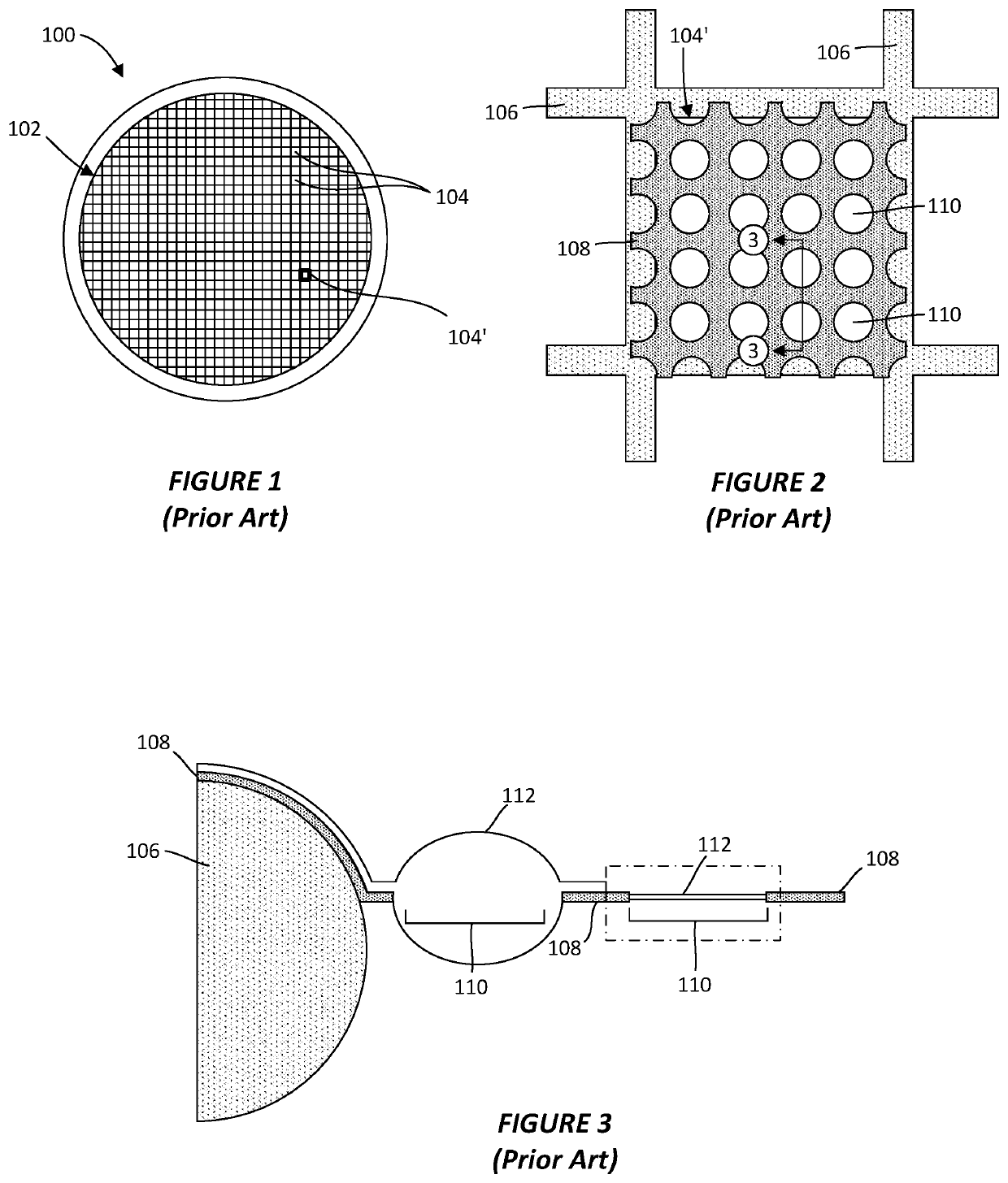
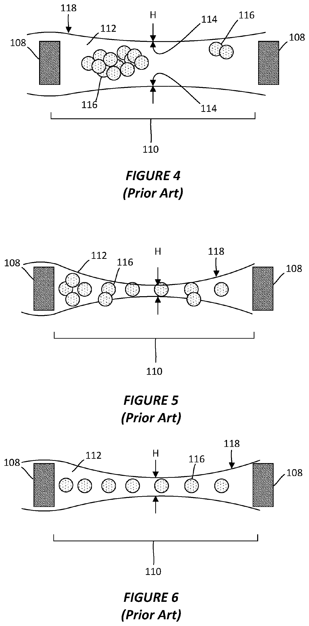
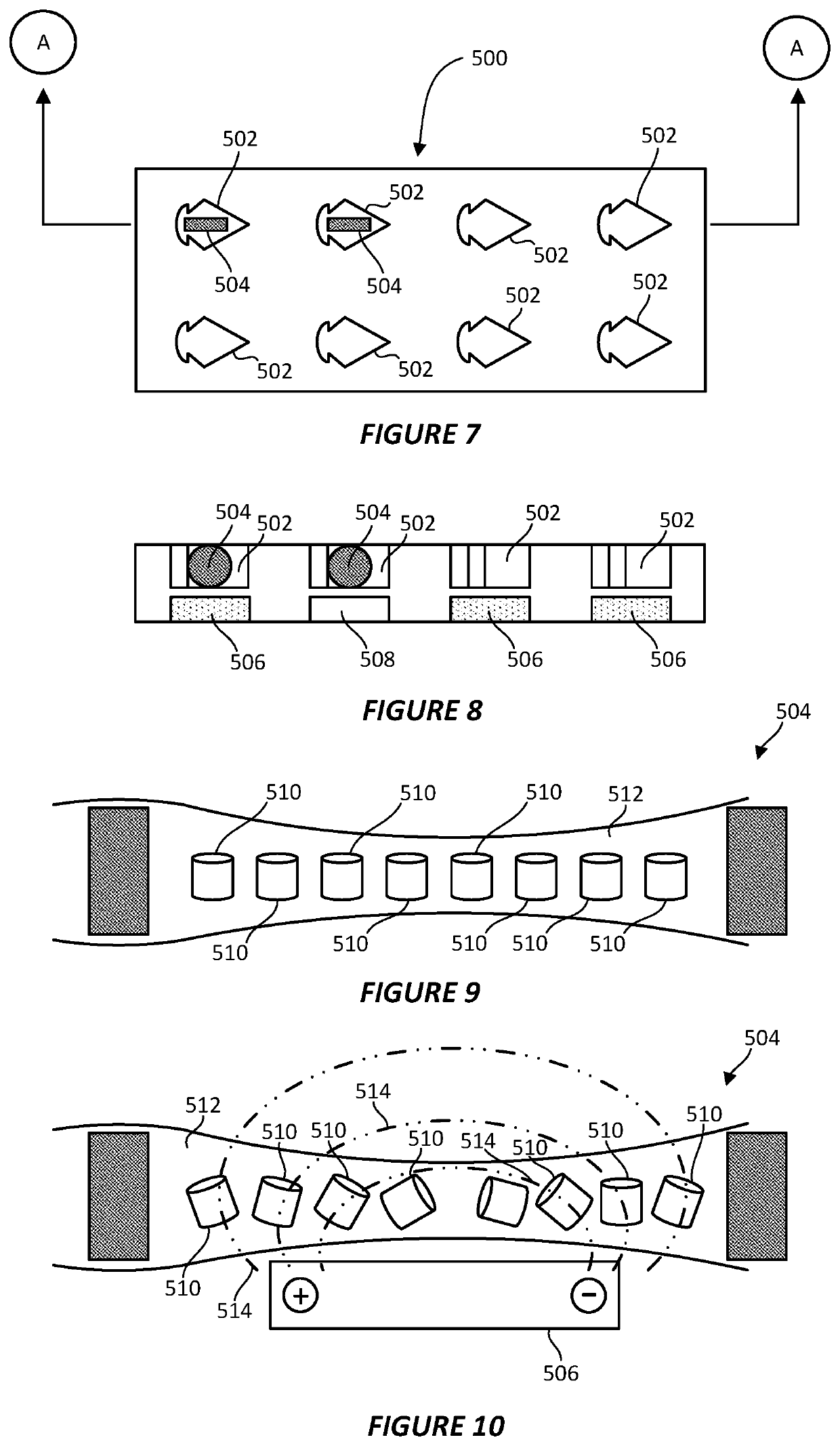
[0039]As discussed above, the protein particles contained within a vitreous ice layer may not be well-dispersed across the ice layer or may not display a sufficient degree of random orientations. To reconstruct its three-dimensional structure, however, the individual protein particles need to be randomly oriented and viewed from multiple angles in a single view. It has been found that, through the application of an electromagnetic field (EMF), the orientation of individual proteins on a sample grid may be reallocated from their preferential and often biased orientation to another...


PUM


Abstract

A system for producing cryogenic electron microscopy (cryo-EM) grids. A grid holding element holds a cryo-EM grid in place while a sample deposit element deposits liquid sample from a sample supply onto the grid. A sample shaping element shapes the liquid sample and then a cryogenic sample vitrifying element vitrifies the liquid sample. The shaping element may direct a gas jet towards the grid to reduce the thickness of the liquid sample. The gas jet may mix first and second liquid samples together in midair or on the grid. A storage element stores vitrified cryo-EM grids and includes an electromagnetic field (EMF) source that creates an EMF within the storage element such that the vitrified sample is exposed to the EMF. As a result of being exposed to the EMF, a protein provided with the sample is re-oriented from a first orientation to a second orientation.

Description

CROSS-REFERENCE TO RELATED APPLICATION[0001]This application is a continuation-in-part of application Ser. No. 16 / 823,506, filed Mar. 19, 2020, entitled SYSTEM AND METHOD FOR PREPARING CRYO-EM GRIDS, which claims the benefit of U.S. Provisional Patent Application No. 62 / 821,857, filed on Mar. 21, 2019, entitled NOVEL DEVICE AND METHOD FOR PREPARING CRYO-EM GRIDS WITH HIGH RELIABILITY, REPEATABILITY AND REPRODUCIBILITY; each of the foregoing applications is incorporated herein by reference in its entirety.TECHNICAL FIELD[0002]This invention relates generally to electron microscopy. More particularly, the invention relates to a method and apparatus for depositing, thinning, and vitrifying liquid samples for use in electron microscopy.BACKGROUND OF THE INVENTION[0003]Part of the research and development cycle of pharmaceuticals is determining how an experimental drug candidate interacts with the body. This is a critical step in learning not only if the pharmaceutical is effective for i...

Claims


Application Information

Patent Timeline
IPC IPC(8): G01N1/42G01Q30/18
CPCG01Q30/18G01N1/42G01Q30/14
Inventor MCQUEEN, TREVOR ALLENLIANG, WINNIE
Owner NEPTUNE FLUID FLOW SYST LLC
Features
  • Generate Ideas
  • Intellectual Property
  • Life Sciences
  • Materials
  • Tech Scout
  • Unparalleled Data Quality
  • Higher Quality Content
  • 60% Fewer Hallucinations
Learn More