Broadband cascaded splitting film array waveguide and display system comprising same

Pending Publication Date: 2020-11-19
BEIJING LLVISION TECH CO LTD
View PDF0 Cites 2 Cited by
  • Summary
  • Abstract
  • Description
  • Claims
  • Application Information

AI Technical Summary

Benefits of technology

[0052]4. The film array adopt the same high refractive index and low refractive index mate

Problems solved by technology

Free-form curved prism, transmitting eyepiece, and other transmitting optical solutions with single-piece type coupler, on the one hand, have a large volume and are difficult to achieve a large field of view and a large exit pupil diameter at the same time.
When the efficiency of light energy is too high, the optical system has poor transmittance and impairs the comfort of use and the indoor experience, and when the external transmission m is high, the efficiency of light energy and the brightness of the virtual image are poor, which is difficult to fulfill the requirement of outdoor applications.
Therefore, how to develop a coupler in a near-eye display system with a large field of view and a large exit pupil diameter, which improves the transmittance and the efficiency of virtual image light energy, has become a problem that those skilled in the art need to solve for a lon

Method used


Image

  • Broadband cascaded splitting film array waveguide and display system comprising same
  • Broadband cascaded splitting film array waveguide and display system comprising same
  • Broadband cascaded splitting film array waveguide and display system comprising same

Examples


Embodiment Construction

[0061]The following describes the implementation process and beneficial effects of the present disclosure in detail through a specific embodiment, and is intended to help readers have an intuitive understanding of the present disclosure, and is not intended to limit the scope of the present disclosure.

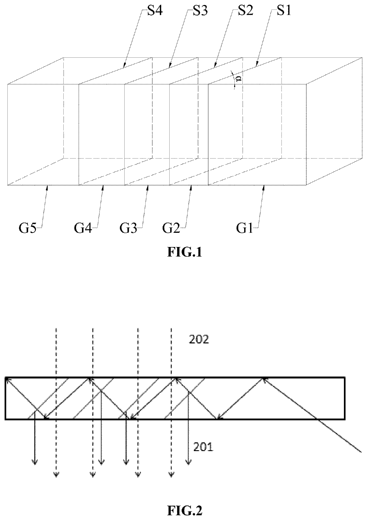
[0062]FIG. 1 is a schematic structural diagram of a thin coating array system suitable for a near-eye display system, which specifically includes glass substrates G1, G2, G3, G4 and G5, and cascaded polarizing films S1, S2, S3 and S4 of a splitting film array, each film is sandwiched between two adjacent glass substrates. Included angle a between bottom surfaces of the glass substrates and the films is 27.5°.

[0063]FIG. 2 is a partial schematic view of light transmitting in an array waveguide, in which a field-of-view light 201 from an image source is shown as solid line, and a field-of-view light 202 from the outside is shown as dotted line. In the plate waveguide, the field-of-view li...


PUM


Abstract

The present disclosure provides a broadband cascaded splitting film array waveguide and a display system comprising the same. The cascaded splitting film array waveguide includes a plurality of glass substrates and a splitting film array, each film of the splitting film array is sandwiched between two adjacent glass substrates and consists of a plurality of H coatings and L coatings alternately arranged in sequence, wherein the H coatings are coatings made of a high refractive index material, the L coatings are coatings made of a low refractive index material, each film of the splitting film array has an even number of coatings, and thicknesses an, pn of the coatings of the film are selected based on the band width and angle of the light beam.

Description

CROSS-REFERENCE TO RELATED APPLICATIONS[0001]This application is a National Stage application of International Application No. PCT / CN2018 / 1115093 filed Oct. 23, 2018, which claims priority to China Patent Application Serial No. CN201711062635.4 filed Nov. 2, 2017.BACKGROUNDField[0002]The present disclosure relates to the technical field of optical displaying, and particularly to a broadband cascaded splitting film array waveguide and a display system comprising the broadband cascaded splitting film array waveguide.Discussion of the Related Art[0003]In recent years, with the emergence of a large number of head-mounted visual devices, for example, Lenovo glasses, Google glasses, glasses for virtual reality (VR) game and likes, virtual reality (VR), augmented reality (AR) and mixed reality (MR) technologies are gradually entering our daily life. Head-mounted devices (HMD, also known as head-mounted visual devices) reflect two-dimensional images directly into the eyes of the viewer. Spe...

Claims


Application Information

Patent Timeline
IPC IPC(8): F21V8/00G02B27/01
CPCG02B27/0172G02B6/0076G02B2027/0123G02B27/0101G02B6/125G02B6/0041
Inventor LI, YONGWU, FEIZHENG, ZHENRONG
Owner BEIJING LLVISION TECH CO LTD
Why Eureka
Try Eureka