Method for preparing the remainder of a donor substrate,substrate produced by said method and use of such a substrate

Active Publication Date: 2020-12-10
S O I TEC SILICON ON INSULATOR THECHNOLOGIES
View PDF13 Cites 0 Cited by
  • Summary
  • Abstract
  • Description
  • Claims
  • Application Information

AI Technical Summary

Benefits of technology

The present disclosure proposes a simpler and less expensive method for preparing a remainder of a donor substrate that results in less material loss than existing methods. The method involves depositing a smoothing oxide on the main face of the remainder and heat-treating it to densify the oxide. The resulting substrate has a layer of the smoothing oxide filling the inner space defined by an annular step, which is a non-removed part of the donor substrate. This method can be used to create a substrate for use in the silicon-on-insulator (SOI) type structure. The technical effects of this patent include reducing material loss, simplifying the preparation process, and improving the quality of the resulting substrate.

Problems solved by technology

These methods are generally complex and comprise the removal of the annular step.
The methods of the prior art are often expensive, long and may lead to a significant loss of material, in particular, for the methods based on “double-sided polishing”.

Method used


Image

  • Method for preparing the remainder of a donor substrate,substrate produced by said method and use of such a substrate
  • Method for preparing the remainder of a donor substrate,substrate produced by said method and use of such a substrate
  • Method for preparing the remainder of a donor substrate,substrate produced by said method and use of such a substrate

Examples


first embodiment

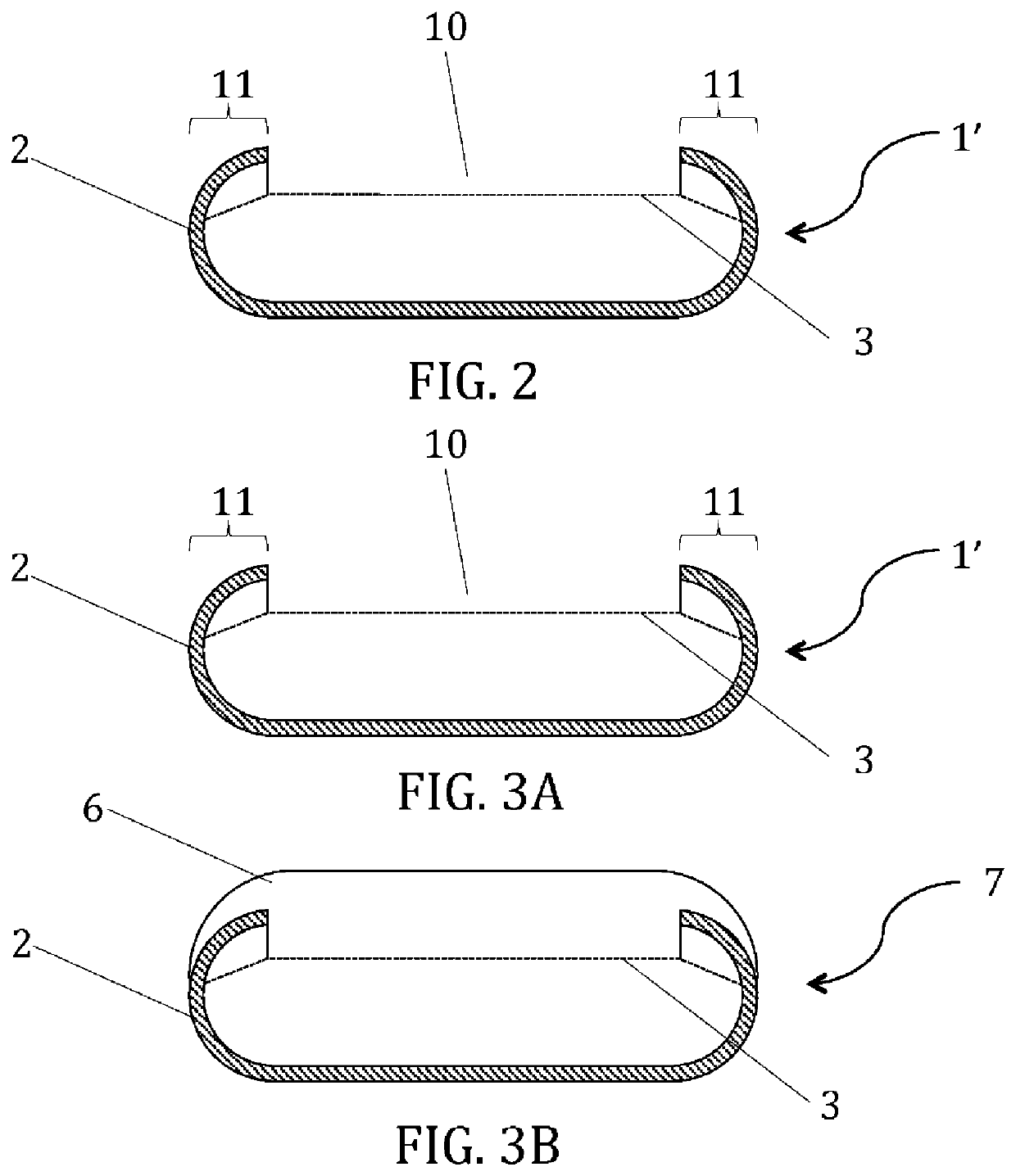
[0045]According to a first embodiment, depicted in FIGS. 3A and 3B, the method for preparing the remainder 1′ comprises two steps: a deposition of a smoothing oxide 6 on the main face 10 of the remainder 1′, and a heat treatment for densification of the smoothing oxide.

[0046]The smoothing oxide 6 is generally selected from the SOG (Spin-On Glass) family, which glasses have the property of being in liquid state at room temperature but may be densified, and made solid, using a suitable heat treatment.

[0047]The step of deposition of a smoothing oxide 6 consists in depositing a layer of smoothing oxide 6 on the main face 10 of the remainder 1′ in order to fill the inner space defined by the annular step 11 and to cover at least part of the annular step 11. The deposition of smoothing oxide 6 may also preferably be carried out under conditions leading to the formation of a layer having a thickness at least equal to one and a half times the height of the annular step 11, as illustrated in...

second embodiment

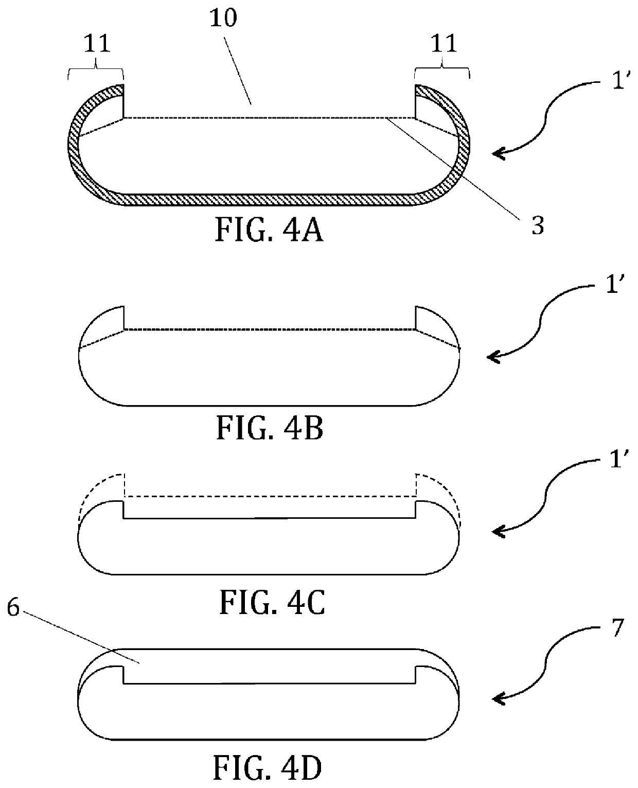
[0052]According to a second embodiment, depicted in FIGS. 4A to 4D, the method for preparing the remainder 1′ comprises an additional step of preparing the main surface 10 of the remainder 1′ before the step of deposition of the smoothing oxide 6.

[0053]Indeed, there is a risk of exfoliation of the annular step 11, or of a part thereof, at the residual implantation defects, when the latter remain present in the remainder 1′ as can be seen in FIGS. 3A and 4A. This problem may arise with the first embodiment even if it is advantageously reduced by covering the step 11 with the smoothing oxide 6, by virtue, in particular, of its viscosity, elasticity, and breaking strength properties. However, it remains possible to further reduce this risk.

[0054]In order to reduce this risk, this second embodiment provides a step of preparing the main surface 10 of the remainder, with the aim of eliminating the part of the step 11 subject to the exfoliation. This step of preparing the main surface 10 o...


PUM

PropertyMeasurementUnit
Temperatureaaaaaaaaaa

Abstract

A method is used to prepare the remainder of a donor substrate, from which a layer has been removed by delamination in a plane weakened by ion implantation. The remainder comprises, on a main face, an annular step corresponding to a non-removed part of the donor substrate. The method comprises the deposition of a smoothing oxide on the main face of the remainder in order to fill the inner space defined by the annular step and to cover at least part of the annular step, as well as heat treatment for densification of the smoothing oxide. A substrate is produced by the method, and the substrate may be used in subsequent processes.

Description

CROSS-REFERENCE TO RELATED APPLICATIONS[0001]This application is a national phase entry under 35 U.S.C. § 371 of International Patent Application PCT / FR2018 / 052938, filed Nov. 21, 2018, designating the United States of America and published as International Patent Publication WO 2019 / 110885 A1 on Jun. 13, 2019, which claims the benefit under Article 8 of the Patent Cooperation Treaty to French Patent Application Serial No. 1761674, filed Dec. 5, 2017.TECHNICAL FIELD[0002]The present disclosure relates to a method for preparing the remainder of a donor substrate. The substrates produced by this method can be used to form an inexpensive structure on insulator of SOI type, for example, for use in the field of microelectronics, for the manufacture of MEMS, etc.BACKGROUND[0003]Smart Cut™ technology is a technology widely used in the semiconductor field for the formation of a thin layer on a support substrate. This technology enables the removal of a thin layer from one face of a donor su...

Claims


Application Information

Patent Timeline
IPC IPC(8): B81C1/00H01L21/762
CPCH01L21/76254B81C1/00357B81C2201/0192H01L21/02032H01L21/02002H01L21/02021H01L21/76259
Inventor DRAZEK, CHARLOTTEBELHACHEMI, DJAMEL
Owner S O I TEC SILICON ON INSULATOR THECHNOLOGIES
Why Eureka
Try Eureka