
Optimal Screened Subsurface Well Design

a subsurface well and optimal technology, applied in the field of multi-level water sampling systems, can solve the problems of not being of a sufficiently low conductivity and unattractive use of wire-wrapped screens with this method, and achieve the effect of facilitating a variety of useful measurement of formation characteristics and lateral conductivity

Active Publication Date: 2020-12-10
KELLER CARL E
View PDF0 Cites 4 Cited by
  • Summary
  • Abstract
  • Description
  • Claims
  • Application Information

AI Technical Summary

Benefits of technology

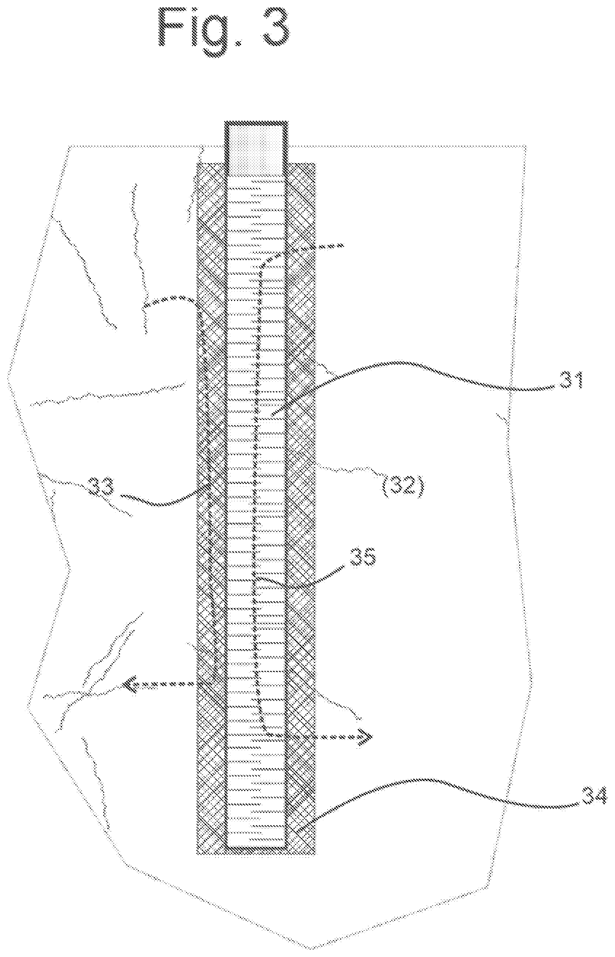
The patent describes a method and system for supporting unstable geological materials surrounding a borehole after drilling. This invention allows for easy access to unstable materials, but also prevents the migration of contaminated formation fluids. Additionally, the invention reduces the vertical migration of contaminants behind a slotted screen in the casing. A very fine-grained sand pack with low horizontal impedance is used to minimize the intermingling of different aquifers due to flow. The interior of the casing is easily sealed with a flexible liner, according to known techniques. The method and system provide a sand pack with higher lateral conductivity than vertical conductivity, which facilitates a variety of useful measurement of formation characteristics in unstable sediments or unstable bedrock wells using devices inside the screened casing. A variation of the method allows for partial or entire sealing of the sand pack after the initial investigation is complete. The design also allows for the identification of the best intervals for subsequent sealing of the sand pack.

Problems solved by technology

(The use of wire-wrapped screens is unattractive with this method.)
(However, the very fine-grained sand pack may allow sand flow through the screen and may not yet be of a sufficiently low conductivity.)

Method used


Image

  • Optimal Screened Subsurface Well Design
  • Optimal Screened Subsurface Well Design
  • Optimal Screened Subsurface Well Design

Examples


Embodiment Construction

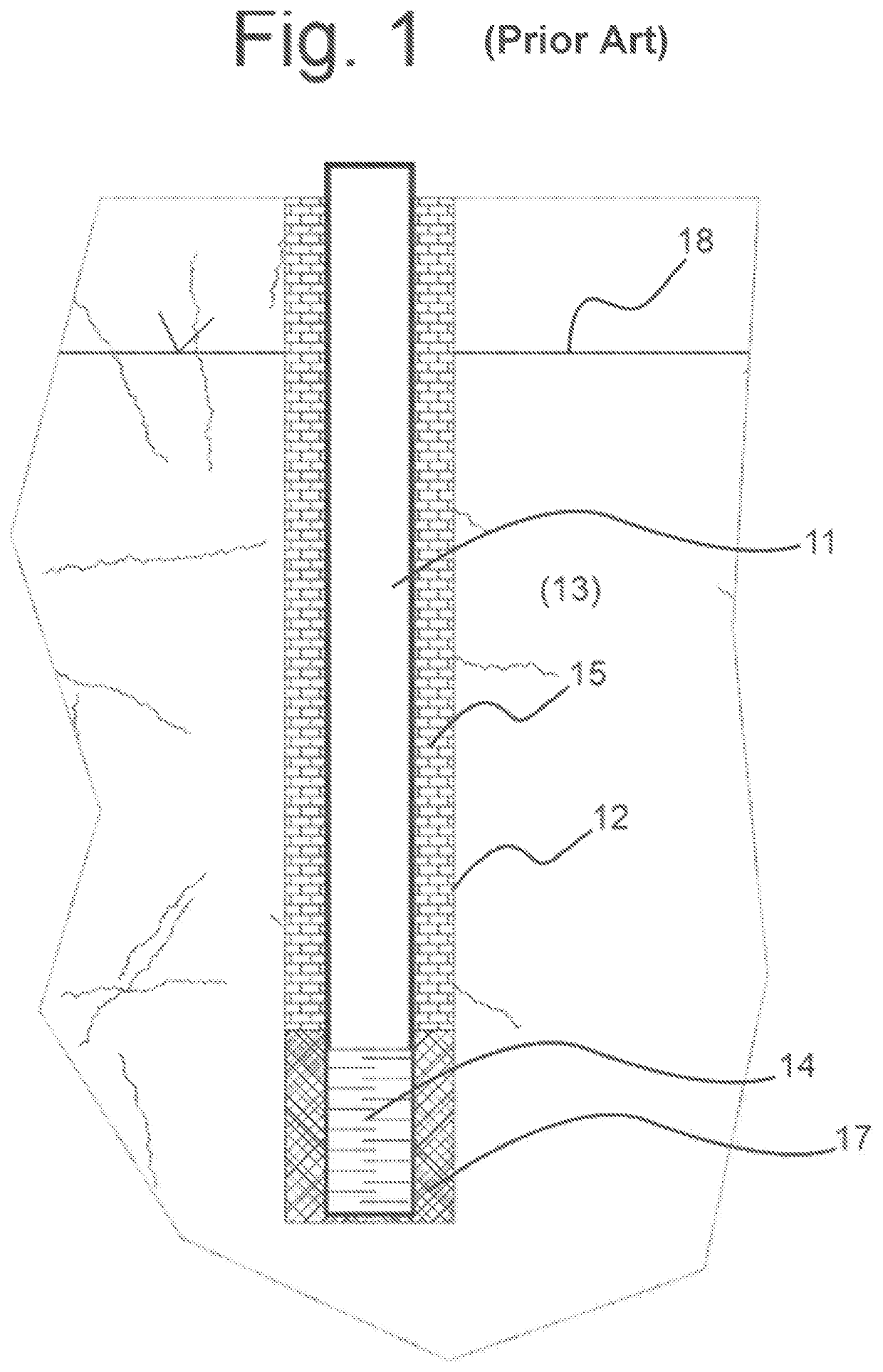
[0026]A traditional and typical borehole well for collection of water samples for analysis is shown in FIG. 1. It includes a casing 11 set in a walled borehole 12 in a surrounding subsurface geologic formation 13. At the bottom end of the casing 11 is a permeable casing section 14 called a “screen,” which may be perforated with holes or slots cut through the casing section to allow water flow from the formation 13, through the casing, and into interior of the casing 11. The annular space 15 between the casing 11 and the borehole wall 12 is filled with a sealing material (e.g., a grout) above the screen 14 (i.e., higher in the borehole than the screen), and with sand 17 in the space between the screen section 14 and the hole wall 12. The slots of the casing screen 14 are smaller than the particles of sand 17 to prevent the sand 17 flowing into the interior of the casing 11. A water sample is obtained from the interval of the screen 14 by emplacing a pump (not shown) below the water t...


PUM


Abstract

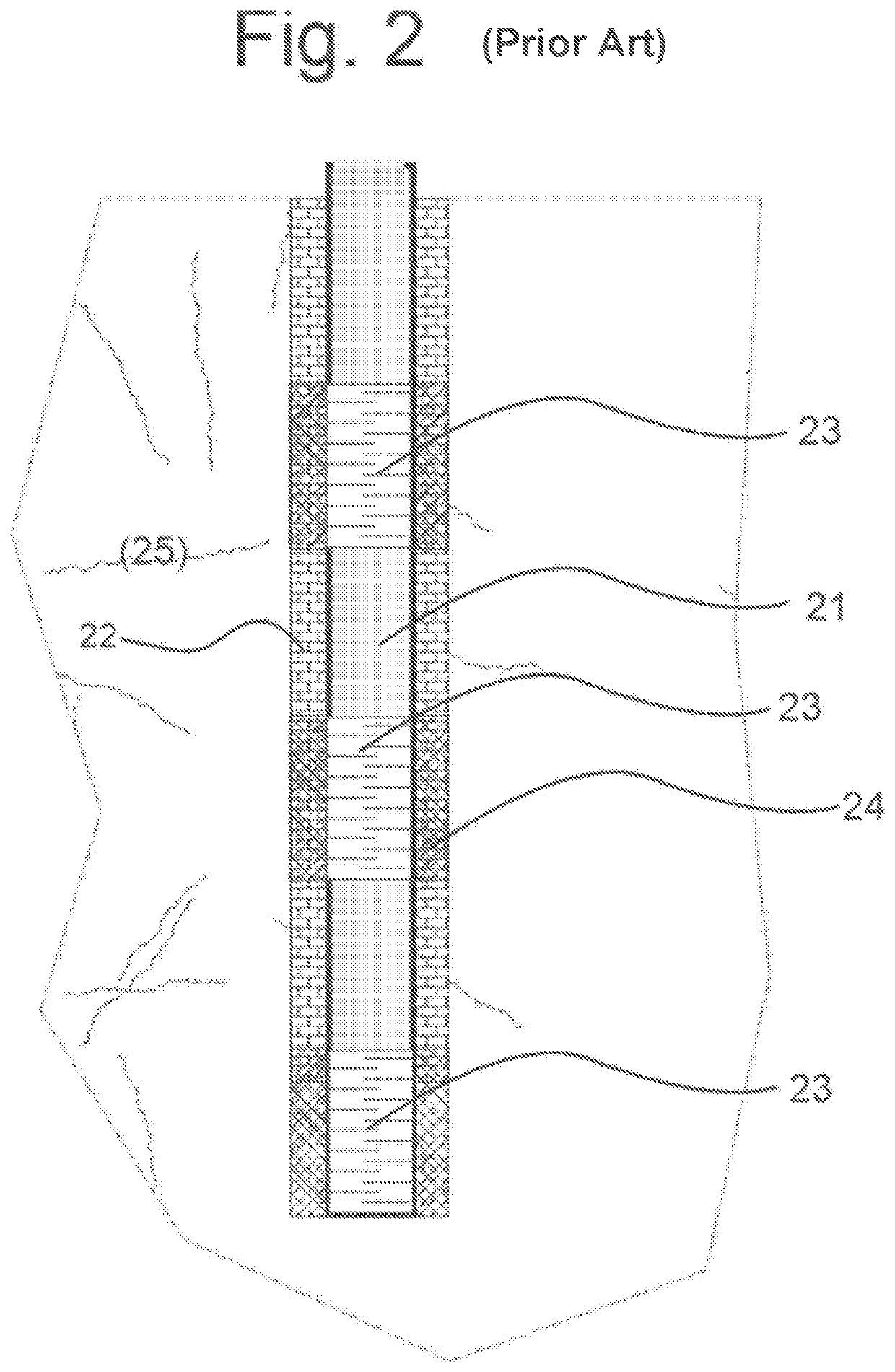
A method and system for supporting unstable geologic materials surrounding a borehole after the borehole is drilled, while reducing the vertical migration in a sand pack behind a slotted screen in the casing. An annulus is defined between a drill casing and a continuous screened casing. Alternating sand fills and sealing layers are deposed in the annulus along a length of the borehole. The length of the sealed interval between the screened casing and the hole wall is reduced, allowing flow connection between the surrounding geologic formation and the interior of the casing over most of the casing length. The sand pack design between the screen and the borehole wall has a sufficient number of sealed barriers to vertical flow to approximate an ideal sand backpacking, which has a vertical conductivity no greater than that of the formation and a relatively low impedance to horizontal flow through the sand pack.

Description

CROSS REFERENCE TO RELATED APPLICATIONS[0001]This application claims priority to and the benefit of the filing of U.S. Provisional Patent Application Ser. No. 62 / 857,938 entitled “Optimal Screened Subsurface Well Design,” filed 6 Jun. 2019, the entire disclosure of which is incorporated herein by reference.BACKGROUND OF THE INVENTIONField of the Invention[0002]This invention relates generally to multi-level water sampling systems within underground boreholes, and more particularly to pore fluid sampling, conductivity measurements, and other similar uses for flexible borehole liners, and specifically to a system, employing a flexible borehole liner, for mapping of ground water contaminant distributions.Background Art[0003]Beneficial reference may be had to U.S. Pat. Nos. 8,424,377, 7,753,120, 6,910,374, and 6,283,209 for background information for the present invention. These patents are incorporated herein by reference.[0004]Flexible liners have been used for many hydrologic measure...

Claims


Application Information

Patent Timeline
Patent Type & Authority Applications(United States)
IPC IPC(8): E21B43/02E21B43/10E21B7/20E21B49/08E21B33/138
CPCE21B7/20E21B33/138E21B49/088E21B43/025E21B49/0875E21B43/10E21B43/08
Inventor KELLER, CARL E.
Owner KELLER CARL E
Learn More