
Wireless power transfer system

a power transfer system and wireless technology, applied in the direction of electrical equipment, safety/protection circuits, batteries, etc., can solve the problems of increasing the weight, potential cost and size of the device, affecting the performance of the device, and affecting the effect of less than optimum performan

Active Publication Date: 2020-12-17
KONINKLJIJKE PHILIPS NV
View PDF0 Cites 6 Cited by
  • Summary
  • Abstract
  • Description
  • Claims
  • Application Information

AI Technical Summary

Benefits of technology

The patent text discusses issues with accurate foreign object detection in power transfer systems, particularly when the power level is high or the load changes frequently. This can lead to false detections or missed foreign objects, which negatively affects communication between the power transmitter and power receiver. Additionally, leakage current and changes in impedance caused by the measurement signal can affect quality factor measurements, resulting in inaccurate data. The text proposes a solution to overcome these challenges and improve the performance of power transfer systems.

Problems solved by technology

However, this tends to be impractical and requires the user to physically insert connectors or otherwise establish a physical electrical contact.
Although, the use of internal batteries may avoid the need for a wired connection to a power supply during use, this only provides a partial solution as the batteries will need recharging (or replacing).
The use of batteries may also add substantially to the weight and potentially cost and size of the devices.
For example, a potential problem with wireless power transfer is that power may unintentionally be transferred to e.g. metallic objects that happen to be in the vicinity of the power transmitter.
The heat increase may be very significant and may be highly disadvantageous.
When the power transmitter detects a significant difference between the power sent by the transmitter and the power received by the receiver, an unwanted foreign object may potentially be present, and the power transfer may be reduced or aborted for safety reasons.
In practice, it tends to be difficult to achieve sufficient detection accuracy using the methods described in the Qi specification.
This difficulty is exacerbated by a number of uncertainties about the specific current operating conditions.
For example, a particular problem is the potential presence of friendly metals (i.e. metal parts of the device that embodies the power receiver or the power transmitter) as the magnetic and electrical properties of these may be unknown (and vary between different devices) and therefore may be difficult to compensate for.
Further, undesirable heating may result from even relatively small amounts of power being dissipated in a metallic foreign object.
Therefore, it is necessary to detect even a small power discrepancy between the transmitted and received power, and this may be particularly difficult when the power levels of the power transfer increase.
However, it may still not provide sufficient accuracy and e.g. may also suffer from the influence of friendly metal.
However, for such a small signal, the signal / noise ratio is typically poor, resulting in reduced accuracy of the measurement.
The requirement for a small measurement signal may result in other disadvantageous effects.
Another issue is that foreign object detection is typically a very sensitive test where it is desired that relatively small changes caused by the presence of a foreign object is detected in an environment with possibly a large variation of the operating conditions and scenarios for which the test is being performed.
Accordingly, current algorithms tend to be suboptimal and may in some scenarios and examples provide less than optimum performance.
In particular, they may result in the presence of foreign objects not being detected, or in false detections of foreign objects when none are present.
The difficulties of accurate foreign object detection are particularly difficult in scenarios wherein the power level of the power transfer signal is high and / or when it varies.
Thus, foreign object detection is particularly difficult during the power transfer phase, and especially for power receivers that represent a large and varying load.
Other operations of the power transfer system may furthermore be sensitive to such effects.
For example, in many situations, communication between the power transmitter and power receiver may be negatively affected by large loads, and in particular by large load variations.
However, such load modulation may be difficult to detect if the power transfer loading of the power transfer signal varies at the same time.
Similarly, communication from the power transmitter to the power receiver may be achieved by modulating the power transfer signal (e.g. amplitude or frequency modulation) but interference to such modulation may be caused by variations in the parameters of the power transfer signal due to a varying load.
Indeed, even if a completely separate carrier is used for communication, such as a NFC communication link, a very large and varying electromagnetic field caused by the power transfer signal may cause substantial interference despite being in a very different frequency band.
Thus, the presence of the power transfer signal, and the loading thereof, may have detrimental impact on other operations, such as foreign object detection and communication operations.

Method used


Image

  • Wireless power transfer system
  • Wireless power transfer system
  • Wireless power transfer system

Examples


Embodiment Construction

[0082]The following description focuses on embodiments of the invention applicable to a wireless power transfer system utilizing a power transfer approach such as known from the Qi specification. However, it will be appreciated that the invention is not limited to this application but may be applied to many other wireless power transfer systems.

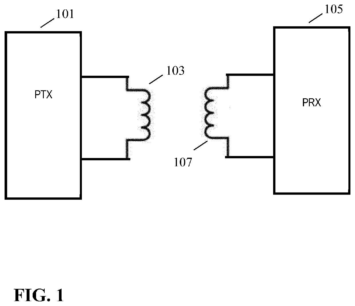
[0083]FIG. 1 illustrates an example of a power transfer system in accordance with some embodiments of the invention. The power transfer system comprises a power transmitter 101 which includes (or is coupled to) a transmitter coil / inductor 103. The system further comprises a power receiver 105 which includes (or is coupled to) a receiver coil / inductor 107.

[0084]The system provides an electromagnetic power transfer signal which may inductively transfer power from the power transmitter 101 to the power receiver 105. Specifically, the power transmitter 101 generates an electromagnetic signal, which is propagated as a magnetic flux by the transmit...


PUM


Abstract

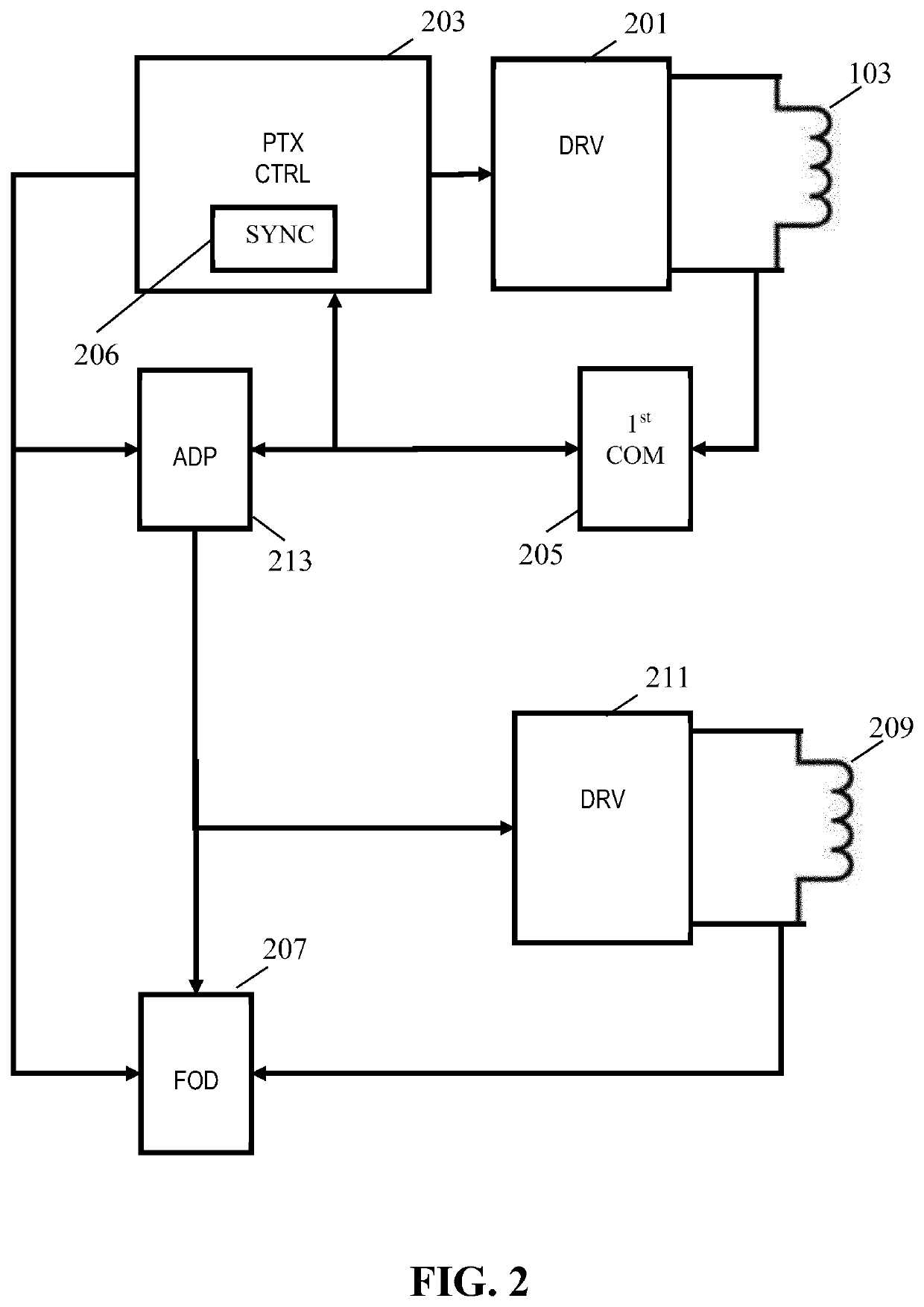
A power transmitter (101) for a wireless power transfer system comprises a transmitter coil (103) and a driver (201) generates a drive signal) for the transmitter coil (103) employing a repeating time frame with a power transfer time interval and a reduced power time interval during which a power level of the power transfer signal is reduced. A driver (201) generates a drive signal for the transmitter coil (103) to generate the power transfer signal. A communicator (205) receives messages from the power receiver (105) and an adapter (213) adapts a timing property of the reduced power time interval in response to at least a first message received from the power receiver (105). A synchronizer (206) for synchronizing a foreign object detection and the generation of a test signal to occur during the reduced power time interval. The operation may typically be a foreign object detection or communication, and the timing property may e.g. be a duration of the reduced power time interval.

Description

FIELD OF THE INVENTION[0001]The invention relates to operation of a wireless power transfer system and in particular to foreign object detection in a wireless power transfer system.BACKGROUND OF THE INVENTION[0002]Most present-day electrical products require a dedicated electrical contact in order to be powered from an external power supply. However, this tends to be impractical and requires the user to physically insert connectors or otherwise establish a physical electrical contact. Typically, power requirements also differ significantly, and currently most devices are provided with their own dedicated power supply resulting in a typical user having a large number of different power supplies with each power supply being dedicated to a specific device. Although, the use of internal batteries may avoid the need for a wired connection to a power supply during use, this only provides a partial solution as the batteries will need recharging (or replacing). The use of batteries may also...

Claims


Application Information

Patent Timeline
Patent Type & Authority Applications(United States)
IPC IPC(8): H02J50/60H02J50/70H02J50/12H02J50/80
CPCH02J50/80H02J50/60H02J50/70H02J50/12H02J50/10H02J7/00308
Inventor ETTES, WILHELMUS GERARDUS MARIAVAN WAGENINGEN, ANDRIES
Owner KONINKLJIJKE PHILIPS NV
Learn More