Method for Inspecting Traction Power Networks

a technology of traction power network and inspection method, which is applied in the direction of instruments, heat measurement, electric devices, etc., can solve the problems of unsatisfactory temperature signal transmission speed, and failure to meet the requirements of a controller with efficient and timely temperature signal transmission, so as to achieve efficient temperature signal transmission, and long temperature signal transmission time

Active Publication Date: 2020-12-24
NANJING INST OF RAILWAY TECH
View PDF0 Cites 0 Cited by
  • Summary
  • Abstract
  • Description
  • Claims
  • Application Information

AI Technical Summary

Benefits of technology

[0010]Accordingly, one of the objectives of the present invention is to provide a method for inspecting traction power networks, which effectively overcome the deficiencies in the prior art, such as low temperature signal transmission speed, long temperature signal transmission time, and failure to meet requirements for a controller with efficient and timely temperature signal transmission.
[0011]Advantages of the present invention are provided as follows. A process of the present invention operable in an intermediate router can efficiently achieve temperature signal transmission, thereby overcoming the deficiency in the exisiting temperature signal transmission mode which is a sequential transmission mode. That is, only when a controller completes transmitting a temperature signal, a subsequent controller is allowed to transmit a temperature signal. If a time interval of a temperature signal transmitted by a controller is not small, other controllers subsequent to the controller will just be on the queue, which results in an unsatisfactory temperature signal transmission speed, long temperature signal transmission time, and failure to meet requirements for a controller with an efficient and timely temperature signal transmission. Furthermore, since the temperature signals are clustered, demand for temperature signal transmission is lower.

Problems solved by technology

If a time interval of a temperature signal transmitted by a controller is not small, other controllers subsequent to the controller will just be on the queue, which results in an unsatisfactory temperature signal transmission speed, long temperature signal transmission time, and failure to meet requirements for a controller with an efficient and timely temperature signal transmission.
Furthermore, since the temperature signals are clustered, demand for temperature signal transmission is lower.

Method used


Image

  • Method for Inspecting Traction Power Networks

Examples


first embodiment

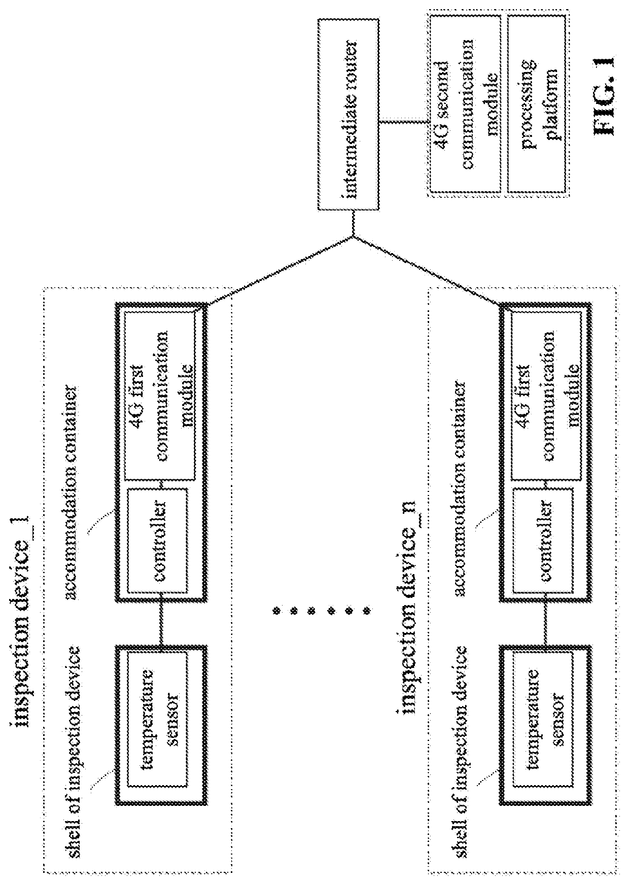
[0021]A a process implemented in the intermediate router includes the following steps executed in sequence:

[0022]A-1: obtaining the temperature signals to be transmitted to the processing platform which are transmitted by the several controllers.

[0023]In step A-1, prior to obtaining the temperature signals to be transmitted to the processing platform which are transmitted by the several controllers, the method further includes: testing whether the link of each of the controllers is unblocked. When the link is tested as unblocked, the temperature signal to be transmitted to the processing platform which is transmitted by each the controller is received. When the link is tested as blocked, the receiving of the temperature signal to be transmitted to the processing platform which is transmitted by each the controller is terminated until the link is tested as unblocked, and then the receiving of the temperature signal to be transmitted to the processing platform which is transmitted by...

second embodiment

[0047]A the process implemented in the intermediate router includes the following steps executed in sequence:

[0048]B-1: verification instructions transmitted by several controllers are received, and the verification instructions contain identification codes of the controllers. In step B-1, the identification codes of the controllers can be determined by specific requirements and can be set as a unique identification code of each controller.

[0049]B-2: searching is performed to check whether any existence of the identification code of the verification instructions transmitted by the several controllers is in identification codes pre-stored in the controllers.

[0050]In particular, the identification code of the controller that can be allow to access is pre-stored, and the searching is performed to check whether any existence of the identification code of the verification instructions transmitted by the several controllers is in the pre-stored identification codes of the controllers.

[00...

third embodiment

[0071]A the process implemented in the intermediate router includes steps executed in sequence as follows.

[0072]C-1: temperature signals to be transmitted to a processing platform which are transmitted by several controllers are obtained.

[0073]C-2: a message to confirm whether the temperature signal to be transmitted to the processing platform is correct is transmitted to each the controller.

[0074]In step C-2, the message to confirm whether the temperature signal to be transmitted to the processing platform is correct is transmitted to each the controller, in which the message has the corresponding temperature signal to be transmitted to the processing platform. For example, in a case with a first controller, a message to confirm whether a temperature signal to be transmitted to the processing platform is correct is transmitted to the first controller, in which the message has the temperature signal to be transmitted to the processing platform which is transmitted by the first cont...


PUM


Abstract

A method for inspecting a traction power network is provided based on a platform which includes a device body of an inspection device for a traction power network apparatus. A power switch is disposed on an outer surface of the device body near a front end thereof, in which a sensitive galvanometer is disposed on the power switch. One end of the sensitive galvanometer is fixedly connected to a temperature sensor coupled to a controller. The controller is coupled to a 4G first communication module coupled to a 4G network. The 4G network is coupled to a processing platform coupled to the 4G network through a 4G second communication module. Other methods and structures are combined to avoid deficiencies in the prior art, such as poor speed and long time in the temperature signal transmission and avoid a controller without meeting requirements for efficient and timely temperature signal transmission.

Description

COPYRIGHT NOTICE[0001]A portion of the disclosure of this patent document contains material, which is subject to copyright protection. The copyright owner has no objection to the facsimile reproduction by anyone of the patent document or the patent disclosure, as it appears in the Patent and Trademark Office patent file or records, but otherwise reserves all copyright rights whatsoever.CROSS-REFERENCE TO RELATED APPLICATIONS[0002]This application claims priority from the China patent application number 201910536064.6 filed Jun. 20, 2019; the disclosure of which is incorporated herein by reference in its entirety.FIELD OF THE INVENTION[0003]The present invention generally relates to the field of techniques inspecting traction power. More specifically, the present invention relates to methods for inspecting traction power networks.BACKGROUND OF THE INVENTION[0004]Traction power equipment is an entire power supply system that transmits electric power to electric locomotives and D-serie...

Claims


Application Information

Patent Timeline
Patent Type & Authority Applications(United States)
IPC IPC(8): B60L3/00B60L3/06G01K1/024G01K7/02
CPCB60L3/0038B60L3/0092B60L3/0084B60L2260/56B60L3/06H04W4/38H04L67/12H04L67/125G01K7/02G01K1/024B60L2200/26Y02T90/16
Inventor SONG, QIHOUFENG, HONGGAOXU, BAICHUAN
Owner NANJING INST OF RAILWAY TECH
Why Eureka
Try Eureka