Methods and apparatus for reducing specular return from wide field-of-view refractive optics

a wide field of view, refractive optics technology, applied in the field of methods and apparatus for reducing specular return, can solve the problems of reducing reducing so as to reduce the optical cross-section of the imager, eliminate the specular return, and reduce the frequency of the specular return

Active Publication Date: 2020-12-24
RAYTHEON CO
View PDF0 Cites 0 Cited by
  • Summary
  • Abstract
  • Description
  • Claims
  • Application Information

AI Technical Summary

Benefits of technology

[0003]As discussed above, specular return, or retro-reflection, from an imaging sensor is highly undesirable as it creates a means by which the location of the imager can be easily and accurately determined. However, due to the lack of an adequate solution to the problem of retro-reflection, particularly in two-dimensional wide field-of-view imagers, the imaging sensor retro-reflection is often simply ignored or discounted as a problem. Aspects and embodiments are directed to an optical design that can be used in refractive imagers to eliminate the specular return from the imaging sensor, which may reduce the optical cross-section of the imager by as much as 1000 times or more, making it much more difficult to detect the imager or identify its location. According to one embodiment, a refractive optical imaging system comprises refractive optics having an entrance aperture and configured to receive optical radiation via an operational aperture, to focus the optical radiation onto a focal plane to form a telecentric image plane co-located with the focal plane, the operational aperture being co-located with the entrance aperture, having a diameter less than half a diameter of the entrance aperture, and being offset from a primary optical axis that bisects the entrance aperture by at least a radius of the entrance aperture. The refractive optical imaging system further comprises an imaging detector disposed at the focal plane and configured to receive the optical radiation, and a blocking component located at the entrance aperture in a region of the entrance aperture not occupied the by the operational aperture, the blocking component being configured to absorb surface reflections from the imaging detector.

Problems solved by technology

As discussed above, specular return, or retro-reflection, from an imaging sensor is highly undesirable as it creates a means by which the location of the imager can be easily and accurately determined.
However, due to the lack of an adequate solution to the problem of retro-reflection, particularly in two-dimensional wide field-of-view imagers, the imaging sensor retro-reflection is often simply ignored or discounted as a problem.
Aspects and embodiments are directed to an optical design that can be used in refractive imagers to eliminate the specular return from the imaging sensor, which may reduce the optical cross-section of the imager by as much as 1000 times or more, making it much more difficult to detect the imager or identify its location.

Method used


Image

  • Methods and apparatus for reducing specular return from wide field-of-view refractive optics
  • Methods and apparatus for reducing specular return from wide field-of-view refractive optics
  • Methods and apparatus for reducing specular return from wide field-of-view refractive optics

Examples


Embodiment Construction

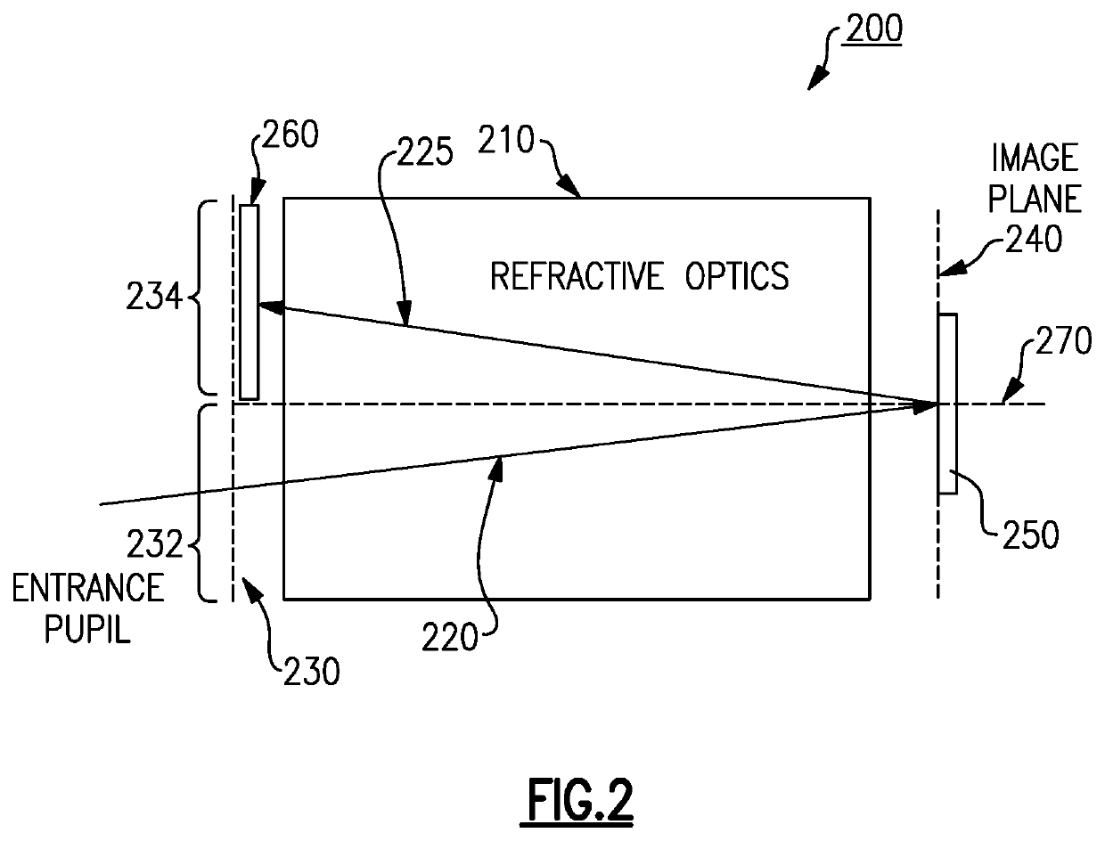
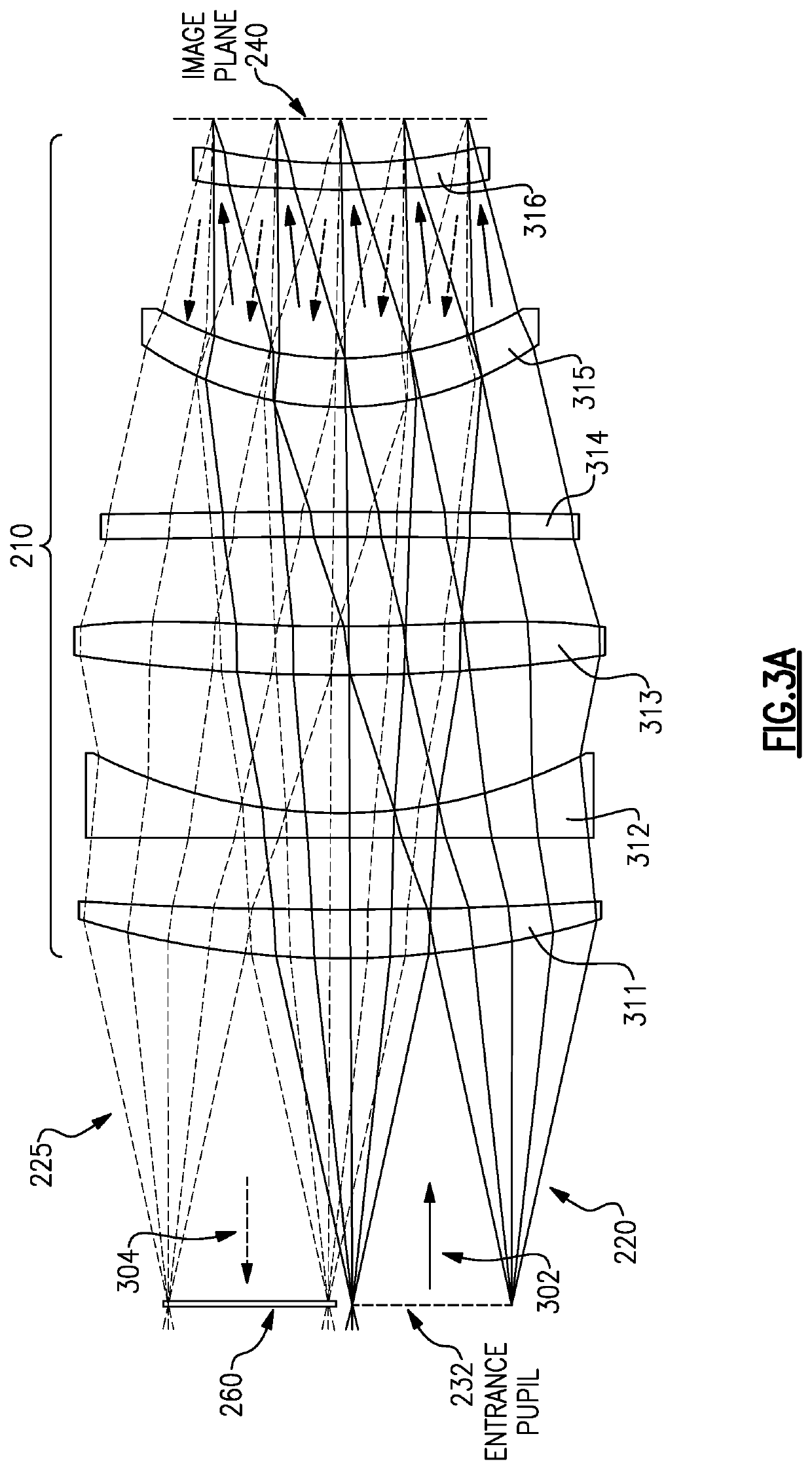
[0019]Aspects and embodiments are directed to an optical design of a two-dimensional wide field-of-view (WFOV) refractive imager that includes an optical design for greater than twice the required aperture for imaging, with the system configured to use only half the design aperture for actual imaging. The other half of the aperture may be used to entirely block any specular reflections from the imager focal plane array (FPA) as such reflections proceed back through the optical train.

[0020]Referring to FIG. 2, there is illustrated a block diagram of an example of an optical imaging system 200, demonstrating this concept. The optical imaging system 200 includes refractive optics 210 that are configured to receive incident optical radiation 220 via an entrance aperture 230 from a viewed scene and focus the optical radiation 230 onto a focal plane 240 at which an imaging detector 250, such as a focal plane array (FPA) sensor, is located. According to certain embodiments, the optical ima...


PUM

PropertyMeasurementUnit
diameteraaaaaaaaaa
field of viewaaaaaaaaaa
transmissionaaaaaaaaaa

Abstract

An optical imaging system including refractive optics and a blocking component. The refractive optical having an entrance aperture and configured to receive optical radiation via an operational aperture, to focus the optical radiation onto a focal plane to form a telecentric image plane co-located with the focal plane, the operational aperture being co-located with the entrance aperture, having a diameter less than half a diameter of the entrance aperture, and being offset from a primary optical axis that bisects the entrance aperture by at least a radius of the entrance aperture, and a blocking component located at the entrance aperture on an opposite side of the primary optical axis from the operational aperture. The blocking component being configured to block the optical radiation from exiting the refractive optics via a region of the entrance aperture where the blocking component is located.

Description

BACKGROUND[0001]Two-dimensional wide field-of-view imagers are typically refractive, and refractive imagers generally have a strong specular return, or retro-reflection, from the imaging sensor (usually a focal plane array (FPA)) over much or all of the field of view. FIG. 1 illustrates an example of a refractive imager 100. The refractive imager 100 includes optics 110 composed of a plurality of refractive optical components (six lenses in the illustrated example) configured to receive incident optical radiation 120 via an entrance pupil 130 (arrow 125 indicating the incoming direction of the optical radiation 120) and focus the optical radiation 120 onto an image plane, or focal plane, 140 where an imaging sensor is located. The example of the imager 100 shown in FIG. 1 receives a collimated input at the entrance pupil 130 of the optics 110 and produces a telecentric or near telecentric image (i.e., the ray cones of the optical radiation 120 are normal to the focal plane 140) at t...

Claims


Application Information

Patent Timeline
Patent Type & Authority Applications(United States)
IPC IPC(8): G02B1/11G02B5/00
CPCG02B5/003G02B1/11G02B23/14G02B27/0018
Inventor COOK, LACY G.
Owner RAYTHEON CO
Why Eureka
Try Eureka