Optical collimation device

Inactive Publication Date: 2020-12-24
COMMISSARIAT A LENERGIE ATOMIQUE ET AUX ENERGIES ALTERNATIVES
View PDF0 Cites 0 Cited by
  • Summary
  • Abstract
  • Description
  • Claims
  • Application Information

AI Technical Summary

Problems solved by technology

However, many light sources do not generate collimated light.
A disadvantage is that the output surface of a collimation lens generally has a curved shape while the input surface of an optical coupler is generally planar, so that there remains a space between

Method used


Image

  • Optical collimation device
  • Optical collimation device
  • Optical collimation device

Examples


Embodiment Construction

[0033]Like features have been designated by like references in the various figures. In particular, the structural and / or functional features that are common among the various embodiments may have the same references and may dispose identical structural, dimensional and material properties. For the sake of clarity, only the elements that are useful for an understanding of the embodiments described herein have been illustrated and described in detail. Unless specified otherwise, the expressions “around”, “approximately”, “substantially” and “in the order of” signify within 10%, and preferably within 5%. In the case where the terms “about”, “approximately”, “substantially”, and “in the order of” are used in relation with a direction or an angle, they mean within 10°, preferably within 5°, of the value in question.

[0034]In the following description, the term useful radiation designates the electromagnetic radiation to be transmitted by the coupler and the term refraction index of a mate...


PUM


Abstract

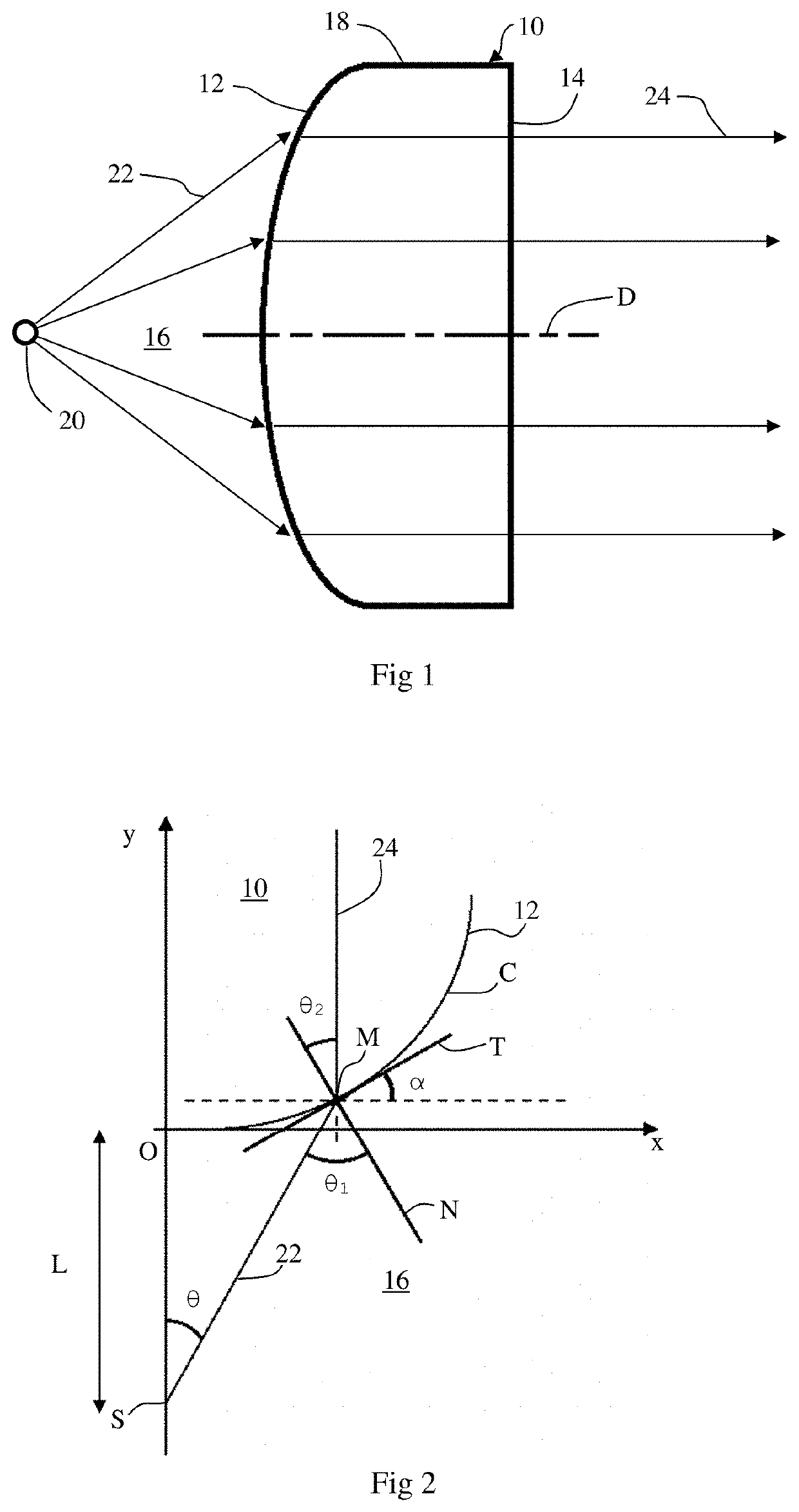
A collimation device of axis D, including a first surface placed in an outer medium having a first refraction index n1 and receiving an electromagnetic radiation delivered by a light source located at a distance L from the first surface, and a second surface delivering the collimated electromagnetic radiation. The collimation device is mainly made of a first material having a second refraction index n2 and the first surface is defined by the revolution around axis D of a profile defined in a plane perpendicular to axis D.

Description


Claims


Application Information

Patent Timeline
Owner COMMISSARIAT A LENERGIE ATOMIQUE ET AUX ENERGIES ALTERNATIVES
Why Eureka
Try Eureka