
Autonomous Utility Cart and Robotic Cart Platform

Active Publication Date: 2020-12-24
MUL TECH LLC
View PDF1 Cites 2 Cited by
  • Summary
  • Abstract
  • Description
  • Claims
  • Application Information

AI Technical Summary

Benefits of technology

The present robotic cart platform can be easily integrated into conventional, manually moved utility carts by adding a drive unit, autonomous mapping and navigation system, environmental mapping and obstacle avoidance sensor, input components and structures that are readily installed on a cart. With minimal modifications to the cart, businesses can inexpensively convert them into autonomous mobile robotic carts. The platform also has weight sensors that measure the weight of the cart, which is used to determine if there is an object on the cart or if the payload is balanced or unbalanced. The cart will then take appropriate action to prevent the loss of the payload or to inform the user of the imbalance. Additionally, the cart detects when a person presses on it, which is recognized as user input.

Problems solved by technology

Second, carts installed with the robotic cart platform keep track of their location when manually pushed to a new location.

Method used


Image

  • Autonomous Utility Cart and Robotic Cart Platform
  • Autonomous Utility Cart and Robotic Cart Platform
  • Autonomous Utility Cart and Robotic Cart Platform

Examples


embodiment 20

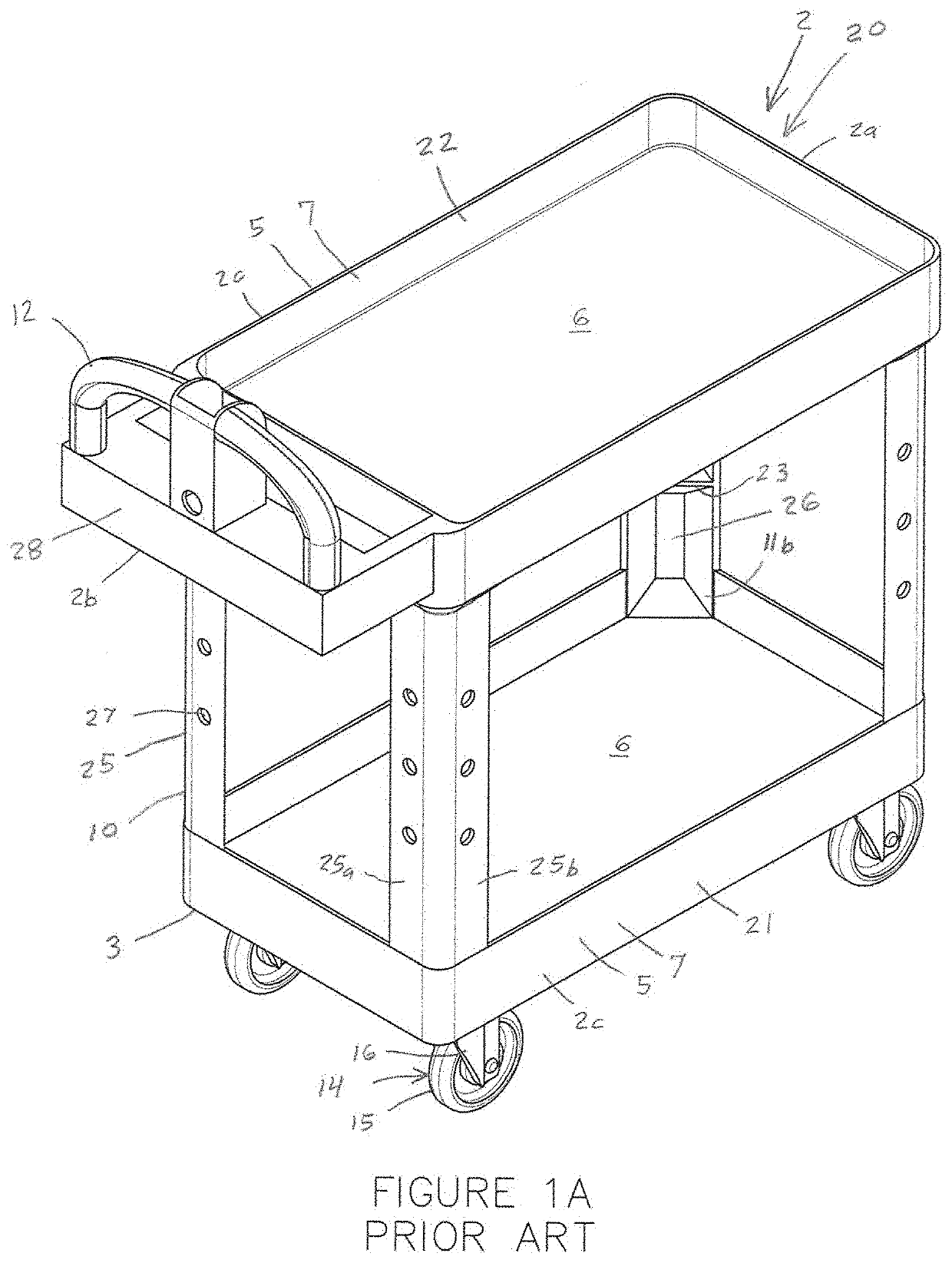
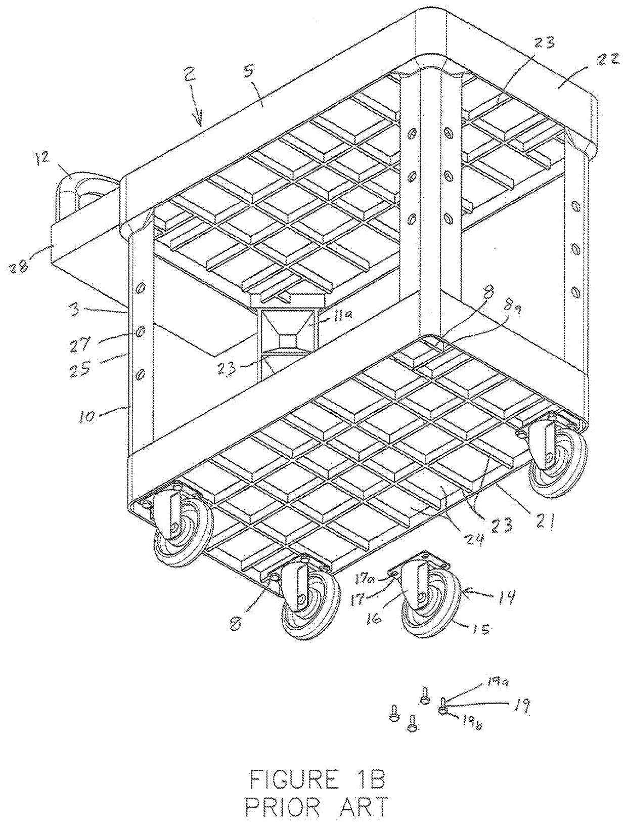
[0043]A plastic embodiment 20 of the conventional utility cart 2 is shown in FIGS. 1A, 1B and 6-9. Although the size and shape of the plastic utility cart 20 can vary, the cart 20 shown has a length of about 39 inches, width of about 17 inches, height of about 33 inches and weight of about 31 pounds, and four caster wheel assemblies 14 with five inch diameter wheels. The cart 20 has two robustly designed plastic trays 21 and 22. The stacked trays 21 and 22 have a rectangular shape and a depth of about 2½ inches. Each tray 21 and 22 has structural webbing 23 supporting its upper surface 6. The webbing 23 forms compartments or openings 24 under the surface 6 of the tray. The solid upper wall or surface 6 of each tray uniformly spans the length and width of the rectangular tray 21 and 22. The cart 20 has four robustly designed plastic risers 25. Each riser 25 has an L-shaped cross-sectional shape with perpendicular sides 25a and 25b that form an inner channel 26 along its vertical leng...

embodiment 30

[0044]A metal embodiment 30 of the conventional cart 2 with its two front caster wheel assemblies 14 removed is shown in FIG. 12. This cart 30 has three robustly designed lower 21, upper 22 and middle 23 wire mesh trays or baskets. The stacked trays 21-23 have a rectangular shape. The corners of the trays 21-23 are joined together by four metal, vertical, tubular risers 35. Each tubular riser 35 has an open interior 36 and an open bottom end 37. The mounting structure 18 of each caster wheel assembly 14 takes the form of a mounting bracket or plate 17 with an upwardly extending mounting post 39. Each mounting post 39 is secured to the cart mounting structure 8, which takes the form of the open bottom end 37 of the tubular risers 35 that receives the post 39 in an in-line manner.

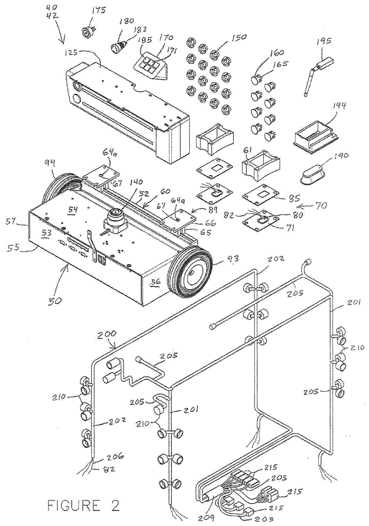
[0045]The present invention pertains to a robotic cart platform system integrated into a conventional cart 2, 20, 30 to form an autonomous robotic cart generally indicated by reference numbers 40 and 45 as sh...


PUM


Abstract

A robotic cart platform with a navigation and movement system that integrates into a conventional utility cart to provide both manual and autonomous modes of operation. The platform includes a drive unit with drive wheels replacing the front wheels of the cart. The drive unit has motors, encoders, a processor and a microcontroller. The system has a work environment mapping sensor and a cabled array of proximity and weight sensors, lights, control panel, battery and on / off, “GO” and emergency stop buttons secured throughout the cart. The encoders obtain drive shaft rotation data that the microcontroller periodically sends to the processor. When in autonomous mode, the system provides navigation, movement and location tracking with or without wireless connection to a server. Stored destinations are set using its location tracking to autonomously navigate the cart. When in manual mode, battery power is off, and back-up power is supplied to the encoders and microcontroller, which continue to obtain shaft rotation data. When in autonomous mode, the shaft rotation data obtained during manual mode is used to determine the present cart location.

Description

TECHNICAL FIELD OF THE INVENTION[0001]This invention relates to a robotic cart platform that converts a conventional manually pushed utility cart into an autonomous utility cart with manual and autonomous modes of operation, tracks the movements of the cart in both modes of operation, warns when unsafe loading conditions occur and is operable with or without a wireless communication system.BACKGROUND OF THE INVENTION[0002]A wide variety of businesses rely on utility carts to move items around inside their buildings. The carts hold and transport tools, equipment, component parts and completed products, many of which are heavy, bulky or awkward to carry, and often include associated paperwork that needs to be kept with an item as it moves from station to station or room to room. The carts come in a wide variety of shapes, sizes and styles. The corners of the carts typically include vertical risers and multiple horizontal trays. The carts are typically made of plastic or metal, and the...

Claims


Application Information

Patent Timeline
IPC IPC(8): G05D1/00B62B3/00B62B5/00G05D1/02B60W60/00B60W50/14
CPCB60W2420/52B60W2530/10G05D2201/0216G05D1/0231B60W2300/40B60W60/0053G05D1/0214B62B5/0053B60W50/14B60W60/0011B62B5/0069B60W2420/10G05D1/0061B62B3/00B60W2050/146B60W2420/22B62B5/0043G05D1/0272G05D1/024G05D1/0274B62B2203/50B62B5/005B60W2420/00B62D63/02G01G19/02B60W2420/408
Inventor ARMBRUST, DANIEL PAULGRABON, ROBERT JAMESJAREMA, RADOSLAW ADAM
Owner MUL TECH LLC
Learn More