Tunable dielectric metamaterial lens device for radar sensing

Active Publication Date: 2020-12-31
IEE INT ELECTRONICS & ENG SA
View PDF0 Cites 8 Cited by
  • Summary
  • Abstract
  • Description
  • Claims
  • Application Information

AI Technical Summary

Benefits of technology

[0044]The at least one antenna member is configured to transmit the radar waves through the metamaterial layer and the at least one receive antenna member is configured to receive the radar waves through the metamaterial layer. A distance between the antenna members and the metamaterial layer is equal to a minimum focal length of the tunable dielectric metamaterial device within predefined limits. By that, an outgoing radar beam of the radar chip can be collimated and can have a minimum beam width. A reconfigurable antenna system able to modify a radar beam pattern or a radar beam direction during operation can beneficially be provided in this way.
[0045]An aperture size of the radar device depends on a beam width of the antenna members and the distance d between the antenna members and the metamaterial layer. In most automotive applications, the distance d will be limited by an integration size of the radar device to roughly 2 cm. A larger aperture, however, has the advantage that a large number of resonators can be used, and a beam shaping resolution increases.
[0046]Preferably, the radar device further comprises a closed housing, which surrounds and supports the at least one radar chip and the tunable dielectric metamaterial device. A portion of the closed housing that is fac

Problems solved by technology

The disclosed sheet resistance range can provide close to optimum performance of the tunable dielectric metamaterial device, as a lower sheet resista

Method used


Image

  • Tunable dielectric metamaterial lens device for radar sensing
  • Tunable dielectric metamaterial lens device for radar sensing
  • Tunable dielectric metamaterial lens device for radar sensing

Examples


Example

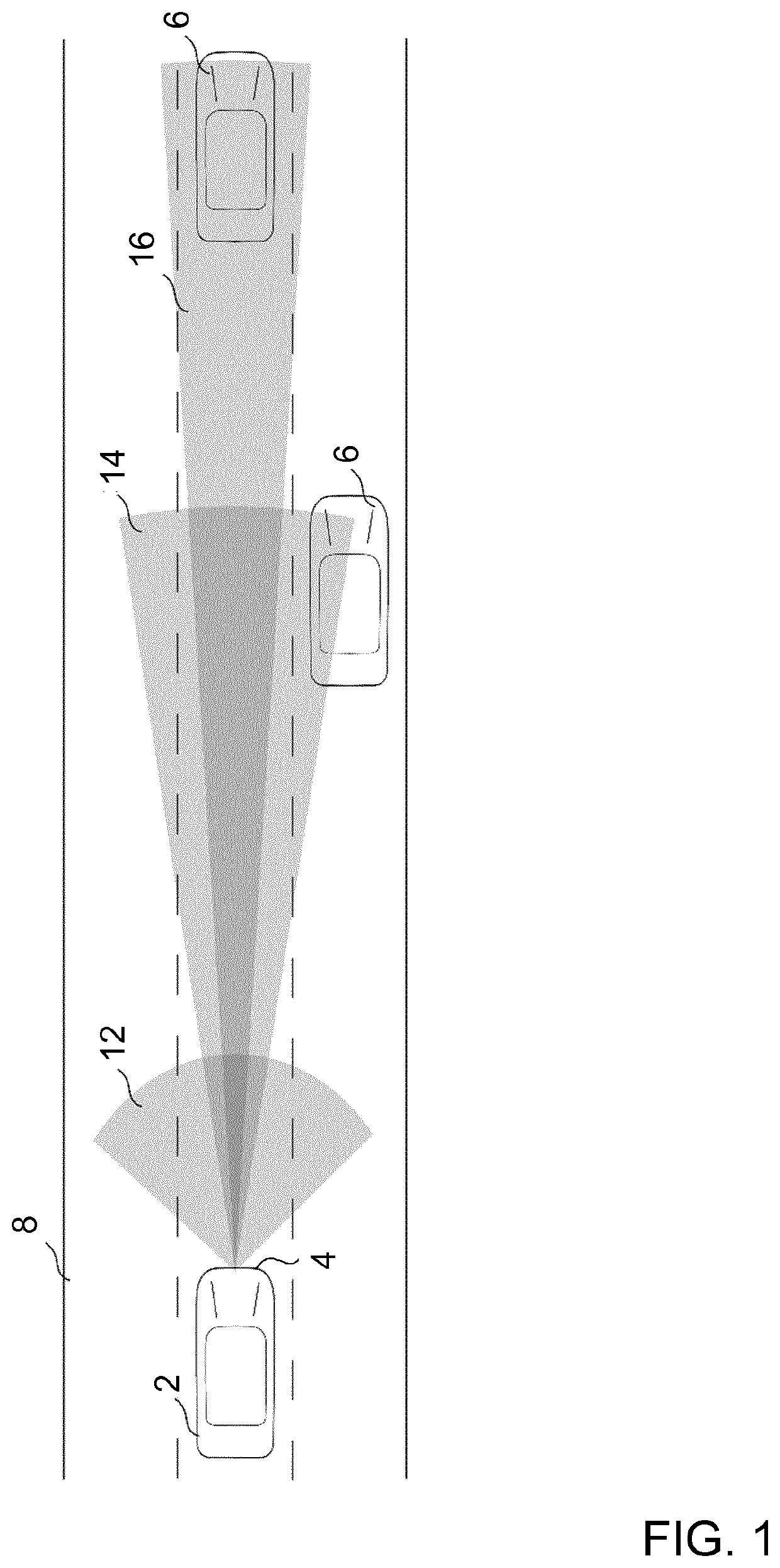
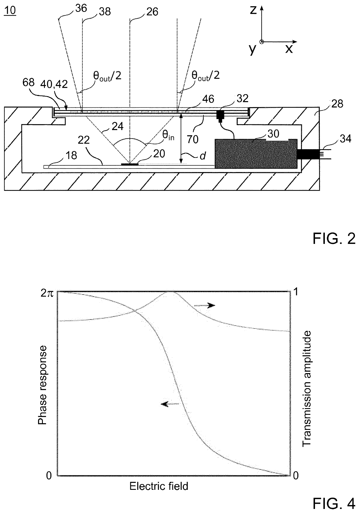
[0063]FIG. 2 shows a schematic side view of a radar device 10 in accordance with an embodiment of the invention. The radar device 10 is particularly configured for use in automotive applications and forms part of the radar system that is installed in the front region 4 of the vehicle 2 designed as a passenger car pursuant to FIG. 1.

[0064]The radar device 10 comprises a radar chip 18, a tunable dielectric metamaterial device 40, a closed housing 28 and control electronics 30. The closed housing 28 surrounds and supports the radar chip 10 and the tunable dielectric metamaterial device 40. A detailed architecture of the radar chip 10 or of the control electronics 30 is of no importance for this application and will therefore not be described in more detail herein.

[0065]An electrical interconnection 32 is provided between the control electronics 30 and the tunable dielectric metamaterial device 40. The control electronics 30 is equipped with a local interconnect network (LIN) interface ...


PUM


Abstract

A tunable dielectric metamaterial device for radar sensing comprises at least one metamaterial layer a plurality of electrically conductive electrodes and a plurality of electrically conductive control lines. The metamaterial layer includes a plurality of dielectric resonators comprising tunable material, wherein at least one electromagnetic property of the tunable material varies with an externally controllable electric field applied to it. Two distinct electrically conductive electrodes each are arranged in a spaced manner at any one of the dielectric resonators to cover the dielectric resonator. The electrically conductive control lines are configured for controlling the electric field to be applied to the tunable material, wherein each electrically conductive line is electrically connected to an electrically conductive electrode. For at least two dielectric resonators, the electrically conductive electrodes that are arranged in the same layer to cover the at least two dielectric resonators are distinct from each other.

Description

TECHNICAL FIELD[0001]The invention relates to a tunable dielectric metamaterial device for radar sensing, particularly for use in automotive applications, and a radar device including such tunable dielectric metamaterial device.BACKGROUND OF THE INVENTION[0002]It is known in the art to employ radar technology in exterior automotive applications, such as driver assistance systems, for providing improved safety by facilitating an optimized reaction of a driver of a vehicle with appropriate warnings, such as vulnerable road user detection systems, lane change assist systems or blind spot monitoring systems, or even by automatically taking over control of the vehicle, for instance in collision mitigation systems. The most common exterior automotive rated devices operate at radar carrier frequencies in regimes about 24 GHz or about 77 GHz.[0003]In the automotive sector, for example, short range and long range radar systems are typically separated. Short range radar systems such as blind ...

Claims


Application Information

Patent Timeline
IPC IPC(8): H01Q15/00G01S7/03H01Q3/46G01S13/931
CPCG01S2007/028H01Q3/46H01Q15/0066H01Q15/0086G01S7/032G01S13/931G01S7/028
Inventor OLK, ANDREASSPIELMANN, THIEMO
Owner IEE INT ELECTRONICS & ENG SA
Why Eureka
Try Eureka