
Allocation and directional information distribution in millimeter wave WLAN networks

a technology of directional information and millimeter wave, applied in the direction of wireless communication, duplex signal operation, assessment restriction, etc., can solve the problems of high data demand, high loss of free-space path, and high penetration

Active Publication Date: 2020-12-31
SONY GRP CORP
View PDF0 Cites 1 Cited by
  • Summary
  • Abstract
  • Description
  • Claims
  • Application Information

AI Technical Summary

Benefits of technology

This approach enhances channel access efficiency and reduces latency by providing explicit directional information, allowing stations to effectively manage channel usage and interference, thereby improving the overall performance of mmWave directional wireless networks.

Problems solved by technology

Current sub-6 GHz wireless technology is not sufficient to cope with high data demands.
High free-space path loss, high penetration, reflection and diffraction losses reduce available diversity and limit non-line-of-sight (NLOS) communications.
This task is further challenging in mmWave communications due to directional transmissions.
In addition, those technologies which utilize directional wireless network communications often have very high overhead demands in regards to the generation of beacon signals.
Still further these technologies lack sufficient mechanisms for reducing the overhead and latencies involved with performing discovery.
The listening phase is usually performed using a quasi-omni antenna, and in many instances this results in channel access being blocked although the transmission or reception direction is not affected by actual directional signal.
However, such approaches would likely show favoritism to nodes with higher gain as compared to others, and would still not optimize channel use.
Explicit directional channel sensing could also be performed, however, this would result in substantial overheads.
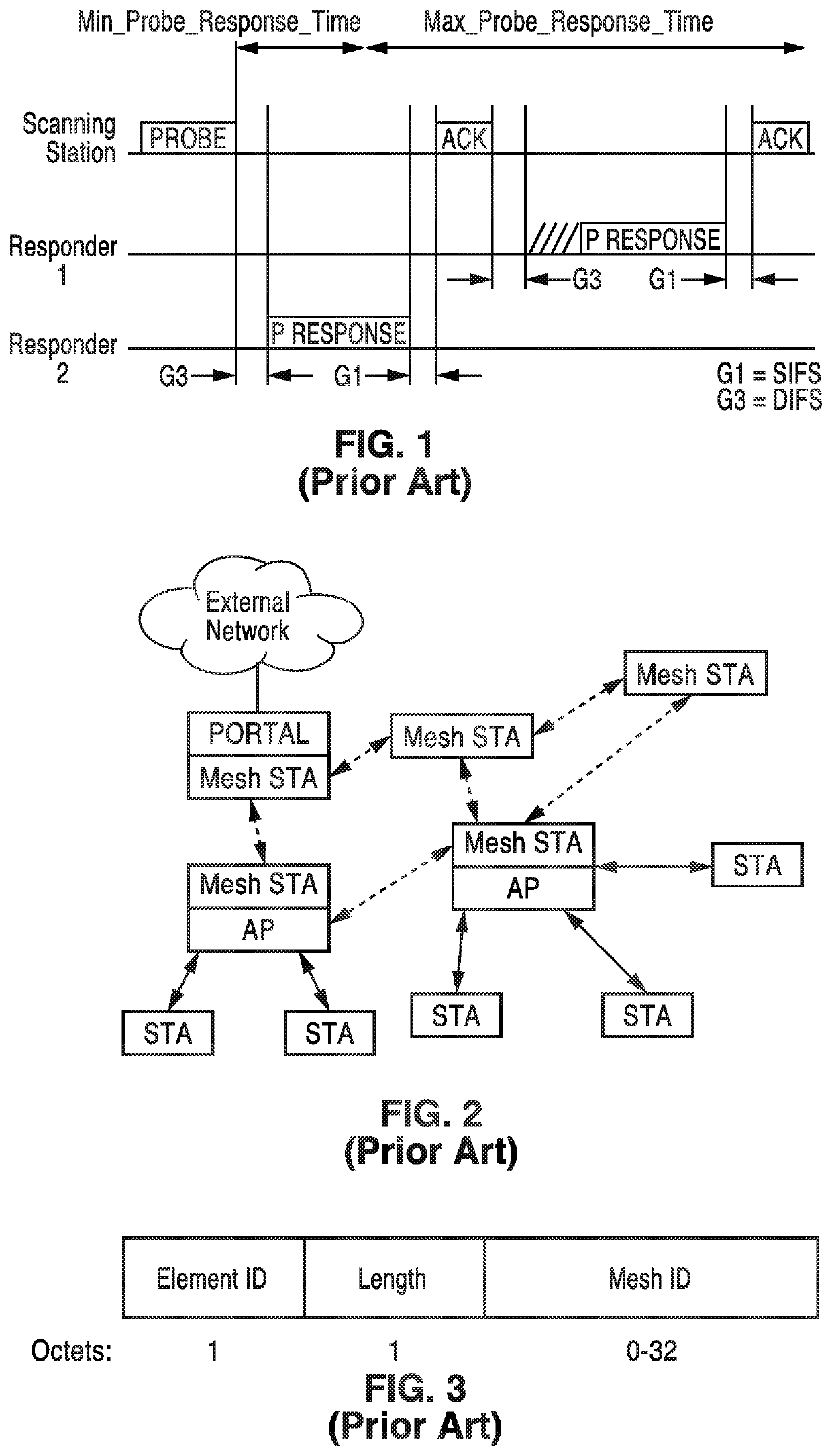
(d) Active scanning can be a source of interference and collision, especially if many new STAs arrive at the same time and are attempting to access the network.
Some of the RF circuitry and antennas may be disabled when the STA determines it is unnecessary to communicate with neighbor STAs.
Some of the mmWave RF circuitry and antennas may be disabled when the STA determines it is unnecessary to communicate with neighbor STAs.
If the STA senses the channel and finds no transmission it should be free to access the channel, however if the CCA failed it might be a false alarm since the STA is communicating in a different direction in relation to the sensed interference.
It will be noted that a direction marked as busy is blocked for access, since some other node is transmitting information in that direction and interference is high.

Method used


Image

  • Allocation and directional information distribution in millimeter wave WLAN networks
  • Allocation and directional information distribution in millimeter wave WLAN networks
  • Allocation and directional information distribution in millimeter wave WLAN networks

Examples


Embodiment Construction

[0049]When used in this disclosure the following terms have the meanings generally described below.

[0050]A-BFT: Association-Beamforming Training period; a period announced in the beacons that is used for association and beamform (BF) training of new stations (STAs) joining the network.

[0051]AP: Access Point; an entity that contains one station (STA) and provides access to the distribution services, through the wireless medium (WM) for associated STAs.

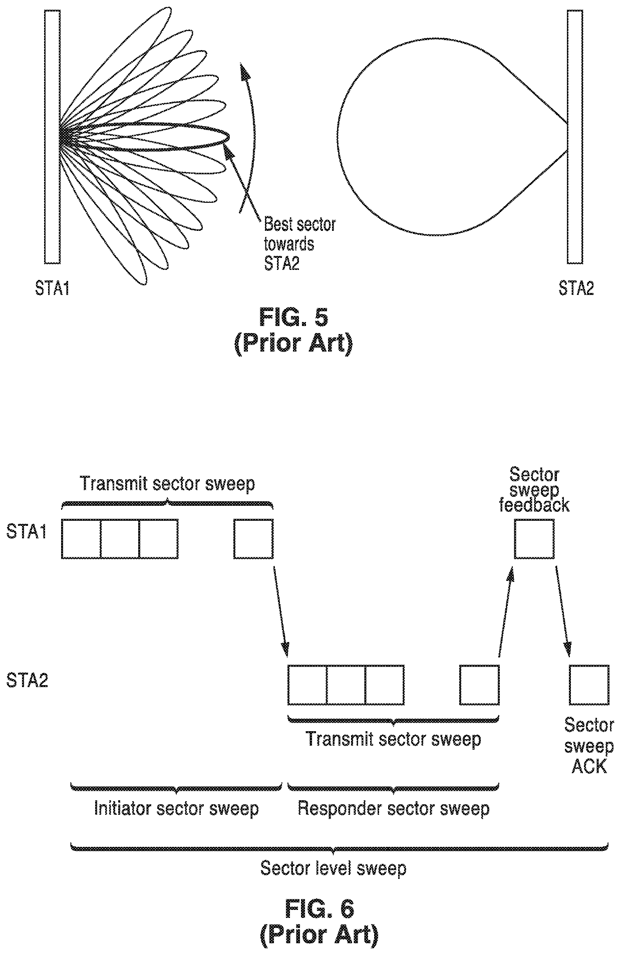
[0052]Beamforming (BF): a directional transmission from a directional antenna system or array, and not an omni-directional or quasi-omni antenna, for determining information for improving received signal power or signal-to-noise ratio (SNR) at the intended receiver, and under which stations can obtain information for correlating time and directional allocation information.

[0053]BSS: Basic Service Set; a set of stations (STAs) that have successfully synchronized with an AP in the network.

[0054]BI: the Beacon Interval is a cyclic super fr...


PUM


Abstract

A wireless communication apparatus, system or method utilizing directional data transmission over a communication (e.g., mmW) band, and broadcasting time and directional allocations in each direction. Stations sending beacons containing time and directional allocations in its direction of transmission. Stations comparing beam identifications with received allocation to determine if the allocation is in the direction of reception. Stations performing receiver beamforming with a station from which a beacon was received in order to determine if the station can access the direction (channel) in its intended direction.

Description

CROSS-REFERENCE TO RELATED APPLICATIONS[0001]This application is a continuation of U.S. patent application Ser. No. 16 / 203,164 filed on Nov. 28, 2018, incorporated herein by reference in its entirety, which claims priority to, and the benefit of, U.S. provisional patent application Ser. No. 62 / 719,782 filed on Aug. 20, 2018, incorporated herein by reference in its entirety.STATEMENT REGARDING FEDERALLY SPONSORED RESEARCH OR DEVELOPMENT[0002]Not ApplicableNOTICE OF MATERIAL SUBJECT TO COPYRIGHT PROTECTION[0003]A portion of the material in this patent document may be subject to copyright protection under the copyright laws of the United States and of other countries. The owner of the copyright rights has no objection to the facsimile reproduction by anyone of the patent document or the patent disclosure, as it appears in the United States Patent and Trademark Office publicly available file or records, but otherwise reserves all copyright rights whatsoever. The copyright owner does not...

Claims


Application Information

Patent Timeline
Patent Type & Authority Applications(United States)
IPC IPC(8): H04B7/06H04W40/24H04W48/16H04W72/04H04L5/14H04W72/12
CPCH04W72/0446H04W72/1263H04W84/12H04L5/1469H04W48/16H04W40/244H04B7/0695H04W72/046H04W74/002H04B7/088H04W74/08
Inventor ABOUELSEOUD, MOHAMED
Owner SONY GRP CORP
Learn More