Method of manufacturing a blood pump

a manufacturing method and blood pump technology, applied in the field of intravascular blood pump, can solve the problems of kinks or breaking, reduced size of the pumping device, and high cost of molds, and the need to be cleaned

Pending Publication Date: 2021-01-07
ABIOMED EURO
View PDF5 Cites 1 Cited by
  • Summary
  • Abstract
  • Description
  • Claims
  • Application Information

AI Technical Summary

Benefits of technology

[0007]It is therefore an object of the present invention to provide an intravascular blood pump having small outer dimensions while at the same time having an efficient electric motor for providing an increased pump rate, as well as a fast and cost-effective method of manufacturing such intravascular blood pump.

Problems solved by technology

However, it is desirable to reduce the size of the pumping device, in particular its diameter, because of anatomical limitations for insertion into a blood vessel.
Furthermore, a relatively long pumping device causes relatively strong kinks at the interface between the pumping device and the flow cannula and the catheter, respectively, during advancing the blood pump through a curved blood vessel, which may lead to kinks or breaking.
Thus, a large number of molds has to be provided for being able to increase the number of produced pieces.
However, the molds are expensive and have to be cleaned after each cycle.
To the contrary, the plastic housing increases the diameter of the pumping device and is heat insulating, which may lead to undesired heating of the electric motor during operation of the blood pump.

Method used


Image

  • Method of manufacturing a blood pump
  • Method of manufacturing a blood pump
  • Method of manufacturing a blood pump

Examples


Embodiment Construction

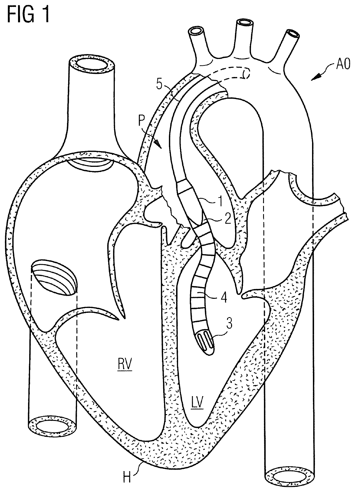
[0041]In FIG. 1 is illustrated an intravascular blood pump P inserted into a patient's heart H. More specifically, the blood pump P comprises a pumping device 1 attached to a catheter 5 by means of which the pumping device 1 is inserted into the left ventricle LV of the patient's heart H to pump blood from the left ventricle LV into the aorta AO. The shown application is only an exemplary application, and the blood pump P of the present invention is not limited to this application. For instance, reverse applications for the right ventricle RV may be envisioned. The blood pump P is percutaneously inserted e.g. via a femoral access or an axillary access and is advanced through the aorta AO into the heart H. The blood pump P is placed such that a blood flow outlet 2 is disposed outside the patient's heart H in the aorta AO, while a blood flow inlet 3 which is in flow communication with a flow cannula 4 is disposed inside the left ventricle LV. An impeller is provided in the pumping dev...


PUM

PropertyMeasurementUnit
outer diameteraaaaaaaaaa
lengthaaaaaaaaaa
lengthaaaaaaaaaa

Abstract

An intravascular blood pump comprises a pumping device including an impeller and an electric motor for driving the impeller. A rotor of the electric motor is rotatable about an axis of rotation and coupled to the impeller so as to be able to cause rotation of the impeller. An outer sleeve forms a casing of the pumping device, wherein stator components are fixed inside the outer sleeve by means of a casting compound. In a method of manufacturing the blood pump the stator components are placed on a molding base, including the outer sleeve to thereby form an interspace between the molding base and the outer sleeve in which the stator components are disposed. The casting compound is then injected into the interspace via the molding base to fix the stator components inside the outer sleeve. The outer sleeve preferably comprises a magnetically conductive material to form a yoke of the electric motor.

Description

FIELD OF THE INVENTION[0001]This invention relates to an intravascular blood pump for percutaneous insertion into a patient's blood vessel, in particular to be advanced into the patient's heart, and in particular a method of manufacturing the intravascular blood pump.BACKGROUND OF THE INVENTION[0002]An intravascular blood pump designed to be inserted percutaneously into a patient's blood vessel, such as a femoral or axillary artery or vein, may be advanced into the patient's heart to act as a left ventricular assist device or right ventricular assist device. The blood pump may, thus, be referred to also as an intracardiac blood pump. An intravascular blood pump typically comprises a catheter and a pumping device attached to a distal end of the catheter. The catheter may contain supply lines, such as an electric line and a purge line. Throughout this disclosure, the term “distal” will refer to directions away from a user and towards the heart, whereas the term “proximal” will refer t...

Claims


Application Information

Patent Timeline
Patent Type & Authority Applications(United States)
IPC IPC(8): A61M1/12A61M1/10
CPCA61M1/125A61M1/1012A61M2207/00A61M2205/273A61M2205/0211A61M60/174A61M60/857A61M60/216A61M60/416A61M60/13A61M60/825A61M60/422A61M60/148B29C65/70B29L2031/7534A61M60/135A61M60/205
Inventor KIRCHHOFF, FRANKPENNERS, JOSEFSIESS, THORSTENCARELL, WERNERKERKHOFFS, WOLFGANG
Owner ABIOMED EURO
Why Eureka
Try Eureka