Method for production of a superconducting magnetic coil

a superconducting magnetic coil and production method technology, applied in the direction of superconducting magnets/coils, instruments, magnetic bodies, etc., can solve the problems of high cost, loss of mechanical stability, and increased temperature over the critical temperature of the superconductor, so as to achieve cost-effective and fast methods, cost-effective production

Inactive Publication Date: 2009-06-09
SIEMENS AG
View PDF9 Cites 2 Cited by
  • Summary
  • Abstract
  • Description
  • Claims
  • Application Information

AI Technical Summary

Benefits of technology

[0014]An object of the present invention is to provide a cost-effective and fast method for manufacturing of a superconducting magnetic coil in which only a minimal contamination of the work space occurs. Furthermore, it is the object of the invention to provide a magnetic resonance apparatus that is cost-effective to produce.
[0016]With this method, the curing of the plastic in which the winding of the superconducting coils is embedded is accelerated by the UV light in comparison to conventional production methods. In this manner the curing of the plastic can be specifically controlled. In comparison to typical wet winding methods in which dripping plastic can contaminate the work space such that the accounting for thickening and curing times extends the workflow, a first curing of the UV-curable plastic can be controlled in a targeted manner such that the UV-cured plastic no longer drips but still retains its tackiness to the extent necessary to allow the layers to bond to one another. After production of the winding a final curing (in particular of the edge layers) can be achieved by irradiation of the winding with UV light.
[0017]The targeted control of the curing of the UV-curable plastics facilitates automation of the workflow, which has a direct advantageous effect in assembly line productions and which expands the possibilities of the quality control during the production.
[0023]In preferred embodiments the UV light is generated by a UV laser and / or a UV lamp. The use of a UV lamp enables a simultaneous curing of larger regions; by contrast the use of a UV laser enables a targeted curing of specific regions that can be cured faster due to the higher intensity of the UV laser.

Problems solved by technology

Due to the severely decreasing heat capacity of all substances at low temperatures, this quickly leads to a temperature increase over the critical temperature of the superconductor.
A number of problems occur with such a production of the magnetic coil.
Pure epoxy resin has a greater thermal coefficient of expansion than the superconducting wire (which is formed essentially of copper), such that upon cooling to the operating temperature of the magnet (4.2 to 10 Kelvin) it exhibits many cracks and thus loses much of its mechanical stability.
The forces must primarily be absorbed by a stable (and thus expensive) winding form.
This means that all regions of the winding may not have a sufficient stability, with the disadvantages described above.
This method has the disadvantage that a contamination of the work space (for example of the winding machine) by dripping epoxy resin occurs.
Both methods exhibit further disadvantages.
For this reason it has conventionally been very time-consuming (and thus uneconomical) to produce a larger self-supporting winding with the wet winding method, since the curing requires a certain time, so the production workflow is significantly lengthened.
The described problems lead to increased production costs, so the manufacturing costs for a magnetic resonance apparatus with a superconducting magnetic coil also increase.

Method used


Image

  • Method for production of a superconducting magnetic coil
  • Method for production of a superconducting magnetic coil
  • Method for production of a superconducting magnetic coil

Examples


Embodiment Construction

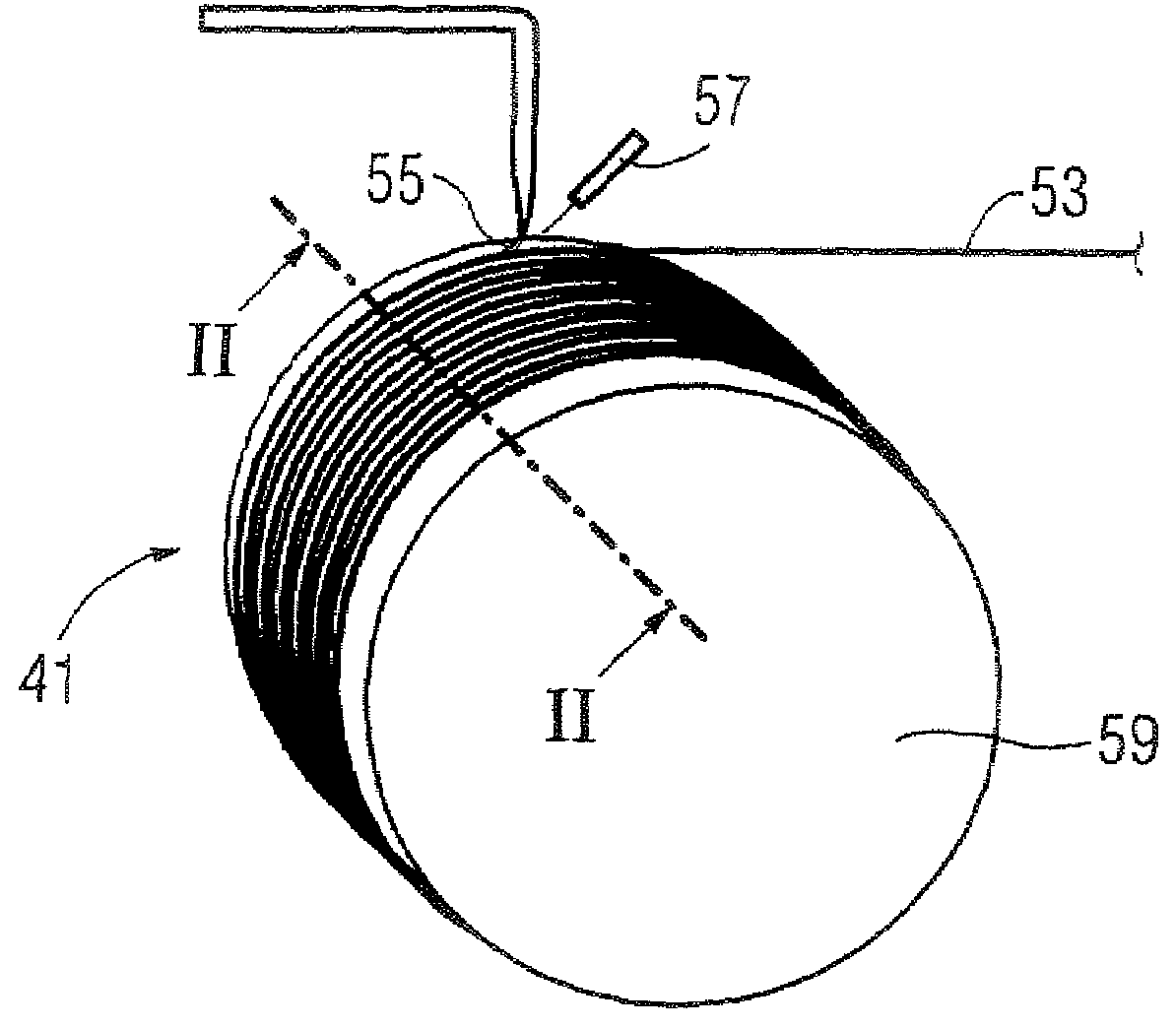
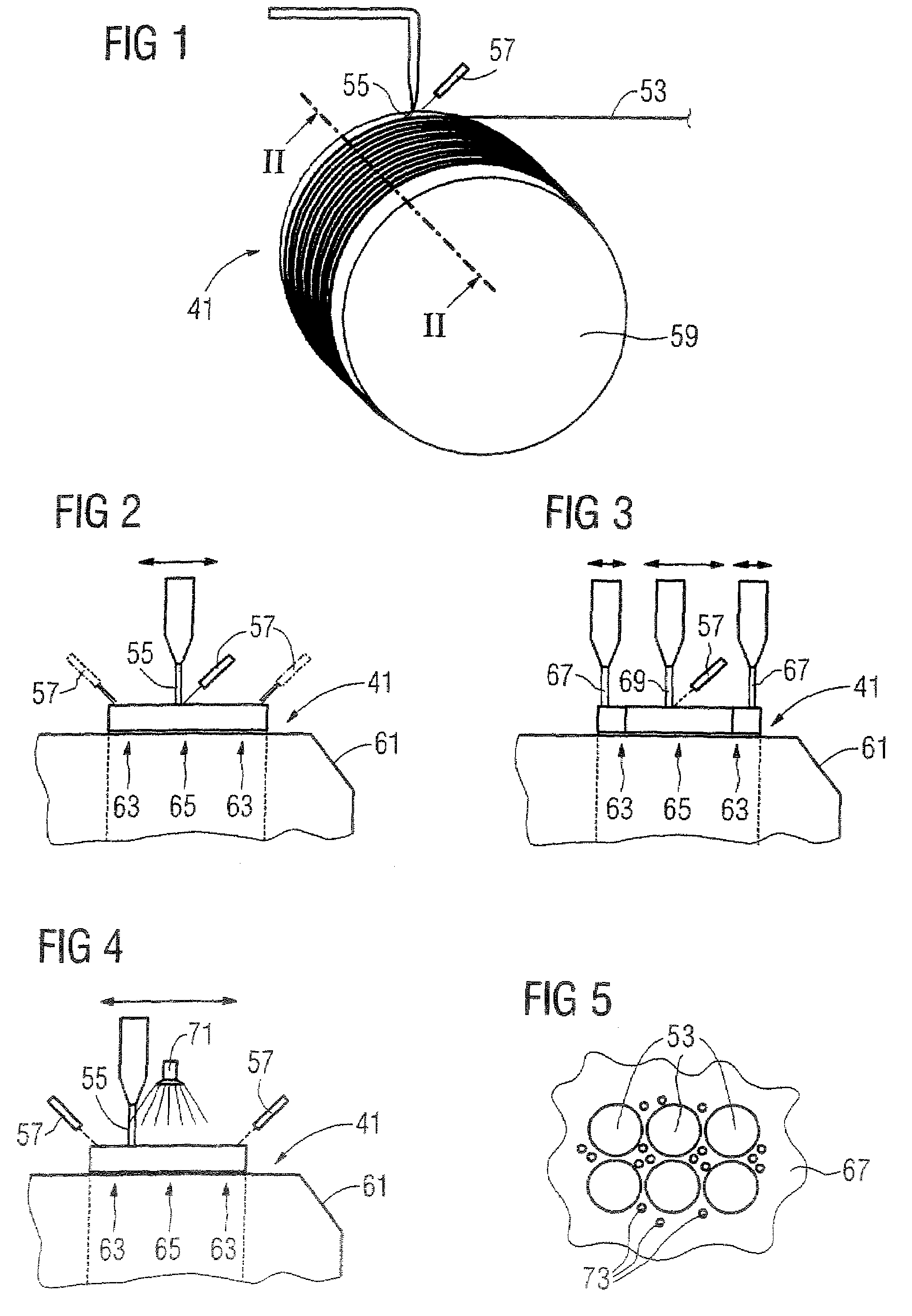
[0036]FIG. 1 illustrates the production of a magnetic coil 41 according to the inventive method. The wire 53 from which the magnetic coil 41 is wound is formed of superconducting material, for example a niobium-titanium alloy in a copper cladding or jacket. Up to multiple kilometers of wire 53 are processed in the winding of a magnet 41.

[0037]In the inventive method the superconducting wires 51 are wound together with a UV-curable plastic 55 that is cured during the winding with UV light (which here is generated by a UV laser 57). The UV-curable plastic 55 is preferably a UV-cured epoxy resin.

[0038]Also shown is a coil form 59 on which the wire 53 is wound and that later is a component of the magnetic coil 41. Conventionally the coil form must be executed relatively stably in conventional methods since it must support and stabilize the wire together with a still-wet plastic, and since it must often absorb a majority of the Lorentz forces. In accordance with the invention a lighter a...


PUM

PropertyMeasurementUnit
magnetic fieldaaaaaaaaaa
superconductingaaaaaaaaaa

Abstract

In a method for production of a superconducting magnetic coil, winding of superconducting wires of the superconducting magnetic coil is implemented with at least one UV-curable plastic, and the UV-curable plastic is at least partially cured with UV light during the winding. A magnetic resonance apparatus has a superconducting magnetic coil that is produced according to this method.

Description

BACKGROUND OF THE INVENTION[0001]1. Field of the Invention[0002]The present invention concerns a method for production of a superconducting magnetic coil of the type used in a cryomagnet, in particular in a cryomagnet of a magnetic resonance apparatus. Furthermore, the invention concerns a magnetic resonance (MR) apparatus with such a magnetic coil.[0003]2. Description of the Prior Art[0004]Magnetic resonance apparatuses have been firmly established in medical imaging for some decades. Image data of a subject to be examined are acquired utilizing the phenomenon of magnetic resonance of atomic nuclei after the application of various magnetic fields, that are tuned as precisely as possible to one another in terms of their spatial and temporal characteristics.[0005]One of these magnetic fields is a static, strong magnetic field with a field strength of typically 0.2 Tesla to 3 Tesla and more. In most cases this magnetic field is generated by a superconducting magnet. The windings of th...

Claims


Application Information

Patent Timeline
Patent Type & Authority Patents(United States)
IPC IPC(8): H01L39/24
CPCG01R33/3802H01F6/06H01F41/048H01F41/122G01R33/3815H01F41/0616Y10T29/49014H01F41/127Y10T29/4902Y10T29/49071Y10T29/49002Y10T29/49073H01F41/066
Inventor BITTNER, GERHARD
Owner SIEMENS AG
Why Eureka
Try Eureka