Interior sewer pipeline scarifying apparatus

Active Publication Date: 2006-06-27
MAC & MAC HYDRODEMOLITION
View PDF18 Cites 0 Cited by
  • Summary
  • Abstract
  • Description
  • Claims
  • Application Information

AI Technical Summary

Benefits of technology

[0009]The present invention relates to an apparatus for scarifying the interior surface of a sewer pipe. A rail assembly matching the circumferential shape of the sewer pipe interior is connected at its ends to a chassis moveable along the bottom half of the sewer pipe. For example, if the configuration of the sewer pipe is semicircular, or cylindrical with a false floor, preferably the rail assembly will be of an arcuate configuration. Preferably, the rail assembly of the present invention will be easily removed from the chassis to allow entry and removal of the apparatus through small openings, such as manholes, into the sewer.
[0014]An advantage of present invention is improved rates of scarifying of the sewer pipe's interior walls. A further advantage is assurance that the same intensity of scarifying is applied to the entire surface without the quality variation that is inherent in manual execution. Further still, the ability of the scarifying head to traverse in either direction of the rail assembly enables a circumferential swath of the interior surface of the sewer pipe to be scarified without requiring the apparatus to make several passes back and forth, resulting in a fast and cost-effective method of scarifying, and making restoration without diversion a cost-effective possibility.
[0015]Lastly, as the configuration of the apparatus enables it to remain in the sewer for the duration of the restoration (i.e. even when waste flow is not at a minimum), this feature results in an increase in productive working time for scarifying the interior surface of the sewer pipe when the sewer flow is at a minimum.

Problems solved by technology

As yet, however, nobody has disclosed a device with an automated process for cleaning or restoring the inside of a pipe that can remain in the interior of the pipe, even under active flow conditions.
In particular, a sewer system's interior walls corrode and deteriorate because corrosive materials contaminate the surface, degrading the metal and concrete used to build the sewer pipe.
The corrosion causes the walls of the sewer pipe to physically decay, eventually reducing their overall thickness.
Eventually the sewer walls must be restored or they can suffer permanent damage leading to great expense.
Attempting to apply a protective coating without first scarifying the pipe surface is futile because it does not stop the decay that has already begun underneath the coating.
Furthermore, the protective coating itself does not adhere well to the contaminated surface.
In practice, the rate of restoration is impaired because manual scarifying takes a proportionally greater amount of time than does the application of the protective coat.

Method used


Image

  • Interior sewer pipeline scarifying apparatus
  • Interior sewer pipeline scarifying apparatus
  • Interior sewer pipeline scarifying apparatus

Examples


first embodiment

THE FIRST EMBODIMENT

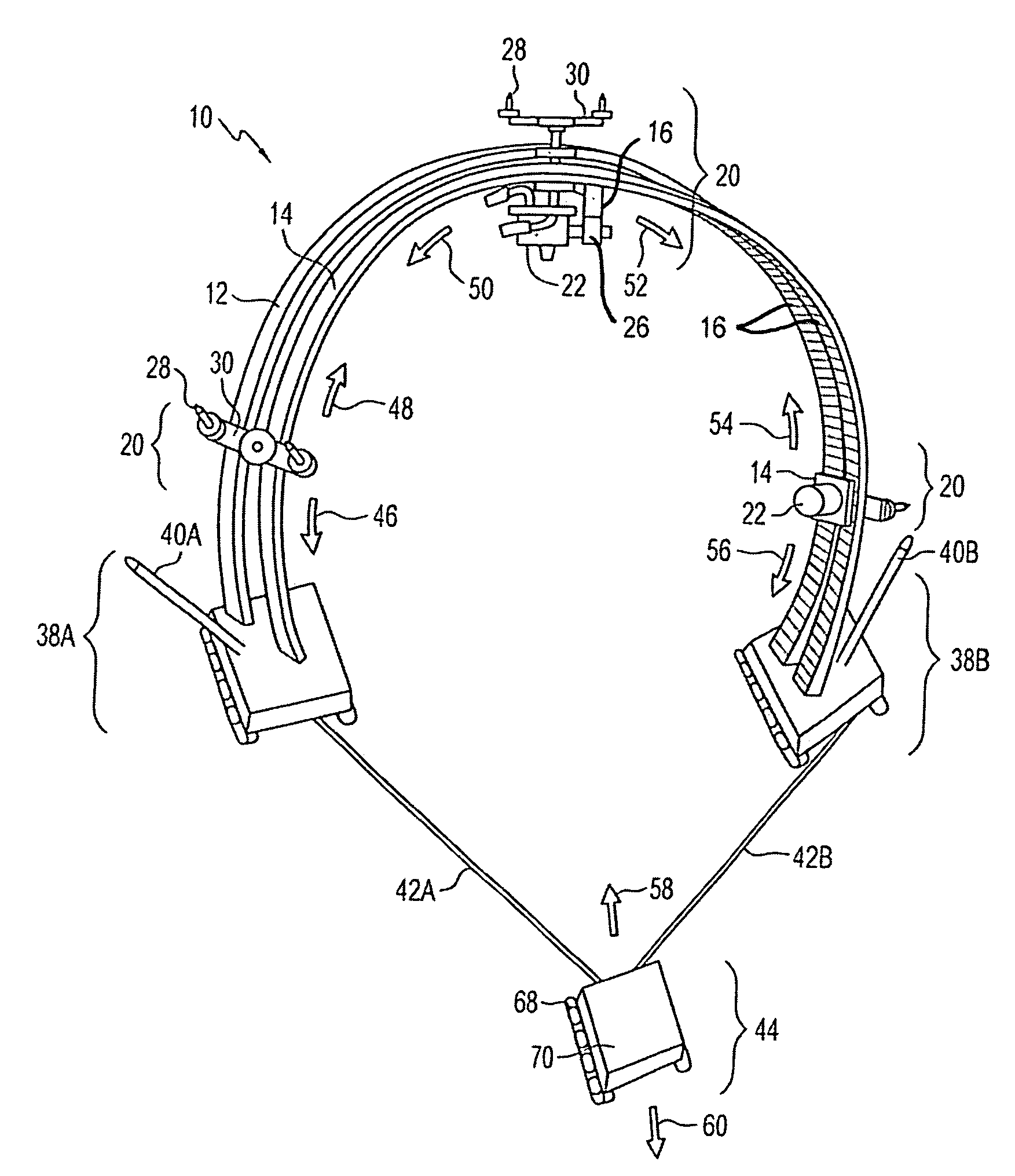
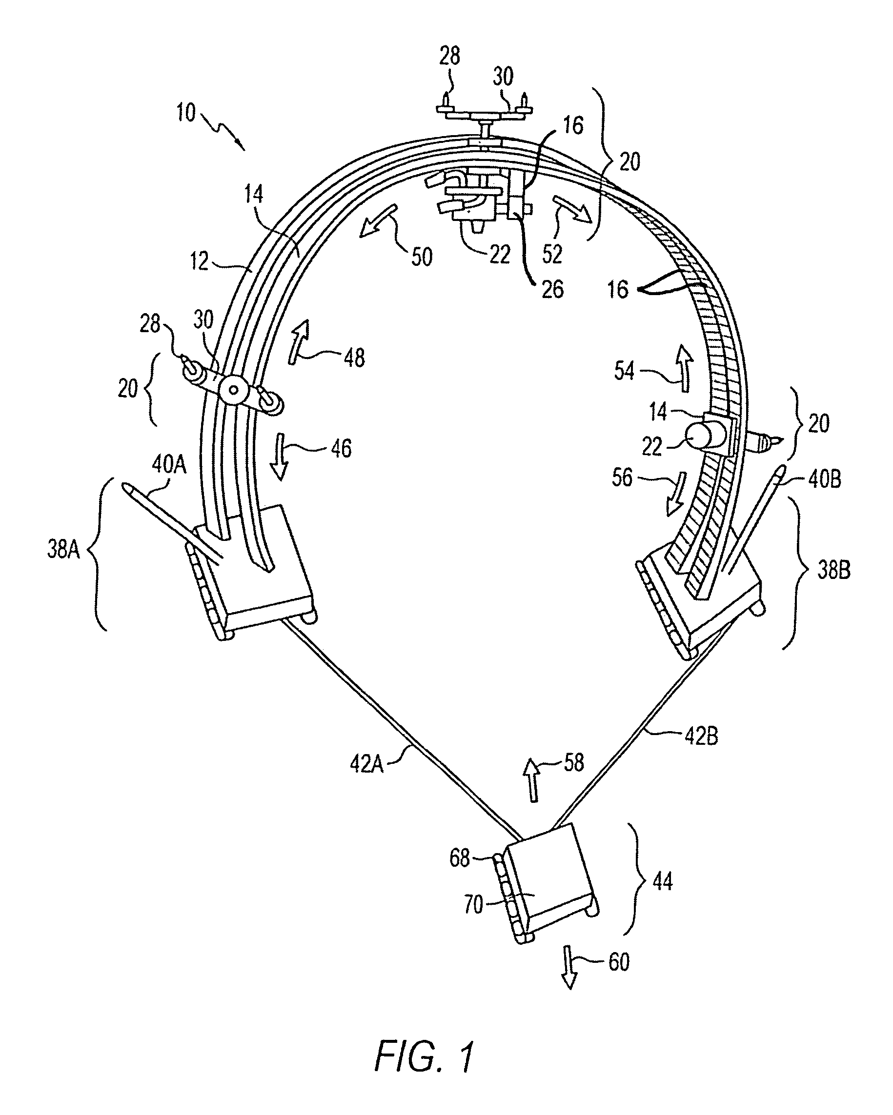
[0026]Referring to FIGS. 1 and 2 a scarifying apparatus 10 includes at least one scarifying head 20 slidably mounted between two arcuate, spaced apart rails 12 and 14. The scarifying head 20 is mounted with a pair of low friction brackets or plates 18 slidably engaging the edges of the rails 12 and 14. A rack 16 is mounted on the underside of one of rails 12 and 14 and a small reversible hydraulic motor 22 mounted on the scarifying head 20 drives a pinion gear 26 which, in turn, engages the teeth of the rack 16, causing the scarifying head 20 to move along the rails 12 and 14. At an outer end of the scarifying head 20 is mounted a pair of outwardly directed nozzles 28 each connected to a respective branch 30, with each branch coupled to an exchanger 32 which receives a single stream of fluid and splits it into two streams of equal flow rate for each of the two nozzles 28. An inlet 31 at another end of the scarifying head 20 is engaged by a hose end 34 and conduct...

second embodiment

The Second Embodiment

[0037]Referring to FIGS. 3 and 4 a second embodiment of the scarifying apparatus 10 includes at least one scarifying head 20 slidably mounted between two arcuate, spaced apart rails 12 and 14. At an outer end of the scarifying head 20 is mounted a pair of outwardly directed nozzles 28 each connected to a corresponding branch 30, with each branch coupled to an exchanger 32 which receives a single stream of fluid and splits it into two streams of equal flow rate for each of the two nozzles. An inlet at another end of the scarifying head 20 is received by a hose end 34 and conducts water to the exchanger 32.

[0038]The exchanger 32 is mounted at the distal end of a telescoping arm, which includes two telescoping pipes in which the upper portion of the pipe 21 has a smaller diameter such that it slides down the lower portion 23. A piston (not shown) controls the extension of the telescoping arm. Consequently, the scarifying head 20 can be manipulated so that the outwa...


PUM


Abstract

This application discloses an apparatus for scarifying the interior surface of a sewer pipe, which can remain in the sewer under active flow conditions. The apparatus includes at least one scarifying head, which may transverse back and forth along a rail assembly, which is configured to match the circumferential shape of the sewer pipe. The scarifying head includes a nozzle assembly and driving assembly. The nozzle assembly, located at the outer end of the scarifying head has nozzles. The nozzles emit jets of water under pressure to clean or scarify the interior surface of the pipe.

Description

RELATED APPLICATIONS[0001]This application is a continuation-in-part of U.S. patent application Ser. No. 10 / 144,705, filed May 15, 2002, and entitled INTERIOR SEWER PIPELINE SCARIFYING APPARATUS now abandoned.FIELD OF INVENTION[0002]The present invention relates to a device for cleaning the interior surface of a pipe and more specifically for cleaning the interior surface of a sewer pipe.BACKGROUND OF THE INVENTION[0003]Pipes used to carry liquids and gases commonly transport all types of materials including water, natural gas and liquid sewage. Over time, these pipes require servicing and cleaning. MacNeil et al. disclose an automated process for cleaning or restoring the inside of a pipe in U.S. Pat. No. 6,206,016. As yet, however, nobody has disclosed a device with an automated process for cleaning or restoring the inside of a pipe that can remain in the interior of the pipe, even under active flow conditions.[0004]The interior surface of a pipeline carrying solids, liquids and g...

Claims


Application Information

Patent Timeline
IPC IPC(8): B08B3/02B08B9/04E03F9/00
CPCB08B9/0433E03F9/00B08B9/051
Inventor MACNEIL, GERARD J.MACNEIL, DAVID B.MACNEIL, GORDON W.BOSE, VERNON G.
Owner MAC & MAC HYDRODEMOLITION
Why Eureka
Try Eureka