
Method of forming an electro-optic medium

a technology of electro-optic medium and electro-optic medium, which is applied in the field of variable transmission devices, can solve the problems of reducing visibility, distracting a viewer, and diminishing the viewing experience in the open state, and achieves the effects of reducing undesirable light scattering, reducing noise, and reducing nois

Active Publication Date: 2021-01-07
E INK CORPORATION
View PDF1 Cites 0 Cited by
  • Summary
  • Abstract
  • Description
  • Claims
  • Application Information

AI Technical Summary

Benefits of technology

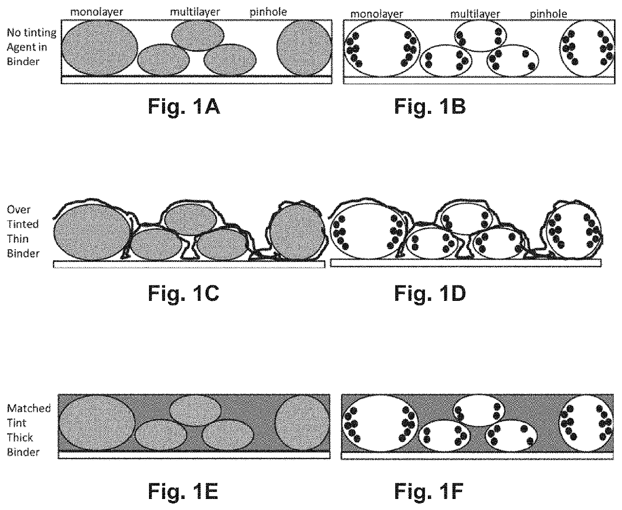
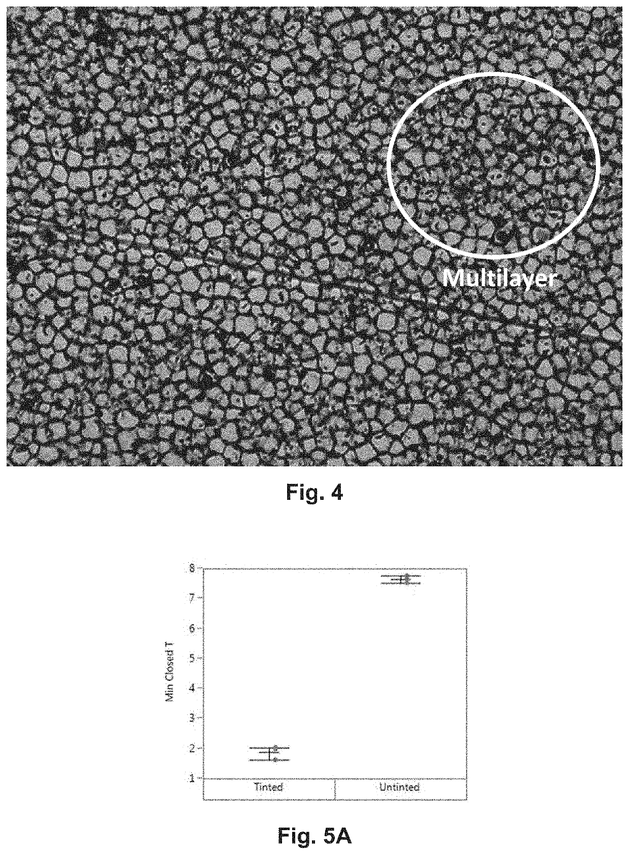
This patent describes a new type of electro-optic medium that includes small capsules filled with fluid and charged particles. These capsules can be opened and closed to control the transmission of light passing through the medium. The binder, or the material that holds the capsules together, should have a similar absorption of light to the capsules when they are closed. This can be achieved by coloring the binder using a dye or a pigment. The patent also describes using fish gelatin and a polyanion to create a better binder for the electro-optic medium. This combination provides low haze and excellent index-matching compared to other binders. Additionally, this binder does not suffer from a specific problem called "kickback."

Problems solved by technology

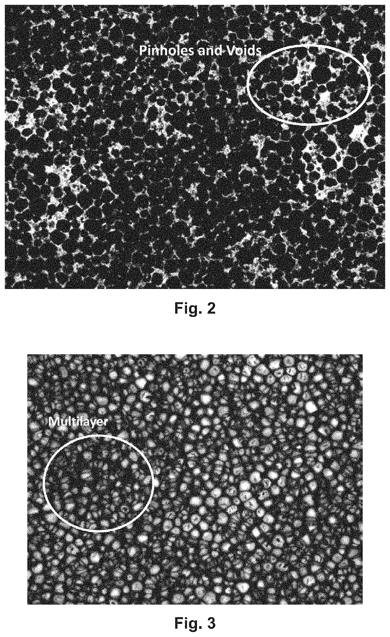
These non-uniformities reduce visibility when a user looks through the device in the open state.
Additionally, the presence of many similar-sized capsules in a close-packed monolayer results in “haloing” or “starbursts” due to interference when viewing light sources through the variable transmission device.
These interference patterns can be very distracting to a viewer, and diminish the viewing experience in the open state.
The impedance mismatch can allow zones of charge to build up between the various materials and influence the position of the electrophoretic particles in the internal phase, resulting in optical-state decay.
Obviously, self-erasing is highly undesirable in that it reverses (or otherwise distorts, in the case of a grayscale display) the desired optical state of the display, or allows a transmissive device to fade from open to closed.
It has been found that self-erasing is a particular problem in polymer-dispersed electrophoretic media and displays, where the capsule is essentially removed from the electro-optic media, leaving only bubbles of internal phase in a polymer binder.
While the tint and speckle are annoying for most applications, they can present safety issues when used for automobile or aircraft glass.

Method used


Image

  • Method of forming an electro-optic medium
  • Method of forming an electro-optic medium
  • Method of forming an electro-optic medium

Examples


example 3

[0122]The displays prepared in Example 2 above containing 2-HDA and OLOA® at a weight ratio of 0.2:1 and Span 85 and OLOA® at a weight ratio of 0.825:1 were subjected to further testing at driving voltages of 45, 60, 90 and 120 V. FIGS. 10A-10D show respectively, the maximum open transmission, minimum closed transmission, minimum open haze and contrast ratio determined in these tests.

[0123]From FIGS. 10A-10D, it will be seen that the display containing 2-HDA exhibited higher maximum open transmission, lower minimum closed transmission, lower open haze and substantially higher contrast ratio under the same conditions as the display containing Span 85. In particular, the Span 85 display failed to achieve the desirable contrast ratio of 30 under any of the tested conditions, whereas the 2-HDA display consistently achieved this contrast ratio at driving voltages of at least 60 V.

example 4

[0124]Displays were prepared as in Example 1 above containing 2-HDA and OLOA® at a weight ratio of 0.2:1 and oleic acid and OLOA® at a weight ratio of 0.4:1. These displays were subjected to testing at driving voltages of 72, 90 and 120 V. FIG. 5 shows the contrast ratios determined in these tests.

[0125]From FIG. 11, it will be seen that the display containing 2-HDA consistently exhibited substantially higher contrast ratios under the same conditions as the display containing oleic acid.

III. Variable Transmission Medium Containing Fish Gelatin:Acacia Binder

[0126]A nonaqueous internal phase was prepared by combining OLOA® 11000, 1-limonene, Cargille® 5040 immersion fluid, carbon black, polystyrene, and 2-hexyldecanoic acid. The internal phase mixture was then encapsulated by adding the mixture to an aqueous gelatin / acacia solution, emulsifying the mixture, and adding a dispersion of 10 wt. % Emperor 2000 carbon black with 5 wt. % Kolliphor P188. After mixing, heating, and pH adjustme...

example 1

[0145]A non-aqueous internal phase was prepared by combining OLOA® 1000, Cargille® 5040 immersion fluid, trans,trans,cis-1,5,9-cyclododecatriene (CDT), carbon black, polystyrene, and 2-hexyldecanoic acid. The resultant mixture was then encapsulated by adding the mixture to an aqueous gelatin / acacia solution, emulsifying the mixture, and adding a dispersion of 10 weight percent Emperor 2000 carbon black with 5 weight percent Kolliphor P 188. After mixing, heating, and pH adjustment, the resulting capsules were cooled and sieved to a range of 20-60 μm, with a mean size of 30-40 μm.

[0146]The resulting capsules were centrifuged and then mixed with an aqueous binder of fish gelatin (Norland HiPure Liquid Gelatin) at a ratio of 1 part by weight binder to 7 parts by weight of capsules, and an aqueous colorant dispersion comprising 10 weight percent Emperor 2000 carbon black with 5 weight percent Kolliphor P188 at a ratio of 1 part colorant dispersion to 49 parts binder. The resultant mixtu...


PUM

PropertyMeasurementUnit
hazeaaaaaaaaaa
hazeaaaaaaaaaa
diameteraaaaaaaaaa

Abstract

A variable transmission film may include an electrophoretic medium having a plurality of capsules and a binder, each capsule containing a plurality of electrically charged particles and a fluid, the charged particles being movable by application of an electric field and being capable of being switched between an open state and a closed state. The film may include at least one of a binder containing fish gelatin and a polyanion; a binder containing one or more tinting agents; capsules containing charge control agents, such as an oligoamine-terminated polyolefin and a branched chain fatty acid comprising at least 8 carbon atoms; a selection of capsules in which at least 60% have a diameter between 50 μm and 90 μm and at least 15% have a diameter between 20 μm and 49 μm; a tinted adhesive layer; and a fluid selected from one or more nonconjugated olefinic hydrocarbons.

Description

CROSS-REFERENCE TO RELATED APPLICATIONS[0001]This application claims the benefit of and priority to U.S. patent application having Ser. No. 16 / 008,180 (filed Jun. 14, 2018), U.S. Provisional patent application having Ser. No. 62 / 520,629 (filed on Jun. 16, 2017), U.S. Provisional patent application having Ser. No. 62 / 520,600 (filed on Jun. 16, 2017), U.S. Provisional patent application having Ser. No. 62 / 520,731 (filed on Jun. 16, 2017), U.S. Provisional patent application having Ser. No. 62 / 520,699 (filed on Jun. 16, 2017), U.S. Provisional patent application having Ser. No. 62 / 563,137 (filed on Sep. 26, 2017), and U.S. Provisional patent application having Ser. No. 62 / 673,743 (filed on May 18, 2018). This application is also related to U.S. Pat. Nos. 7,256,766; 7,327,511; 7,679,814; and 7,999,787.[0002]The entire contents of these applications, patents, and of all other U.S. patents and published and copending applications mentioned below, are herein incorporated by reference in th...

Claims


Application Information

Patent Timeline
Patent Type & Authority Applications(United States)
IPC IPC(8): C09B67/08G02F1/167G09G3/34G02F1/1677G02F1/16757G02F1/1676B82Y30/00G02F1/1675
CPCC09B67/0013G02F1/167G09G3/344G02F1/1677G02F1/16757G02F2202/28G09G2320/0233G02F2202/022B82Y30/00G02F2001/1678G02F1/1676G02F1/1675
Inventor WIDGER, PETER CARSTEN BAILEYANSETH, JAY WILLIAMPAOLINI, JR., RICHARD J.ROMANOWSKY, MARK BENJAMINSMITH, JILLIANTELFER, STEPHEN J.BREEN, CRAIG ALANBULL, STEPHEN
Owner E INK CORPORATION
Learn More