Relay conditioning and power surge control

a technology of relay contact and power surge control, which is applied in the direction of emergency protective arrangements, emergency power supply arrangements, and coupling device connections, etc., can solve the problems of catastrophic failure, damage to solid-state switching components, and relay contact liquidation, etc., to reduce instantaneous impedance and low values

Pending Publication Date: 2021-01-07
ZONIT STRUCTURED SOLUTIONS LLC
View PDF0 Cites 4 Cited by
  • Summary
  • Abstract
  • Description
  • Claims
  • Application Information

AI Technical Summary

Benefits of technology

[0012]This issue can affect any relay based or solid-state based ATS, making them malfunction and / or fail. This can cause unintended downtime to occur for AC / DC powered equipment due to the ATS not working. This can cause serious problems if mission critical equipment goes down due to power delivery failing. It can be appreciated by the user that designers of EDP and other equipment types that are targeted for data center use often assume that the power quality in the data center is well controlled and of good quality. Therefore use of traditional methods to protect from transient power spikes is often limited and / or absent. The other problem with traditional methods are that they often are too big to be used in crowded data center cabinets with limited free space and form factor limited devices. The present invention provides a number of devices and methods to increase the odds or positively prevent ATS units or other devices from failing due to these conditions and meet the other constraints, such as form factor, energy efficiency, cost, etc. that data center and other environments often require.
[0027]In accordance with a still further aspect of the present invention, a system is provided for use in conditioning a contact surface of an automatic transfer switch. As noted above, it is been found that a contact surface can be conditioned to change the morphology of the contact surface, thereby rendering an automatic transfer switch less susceptible to damage due to power surges. A system can thus be provided to condition the contact surface by applying a power signal directly to the contact surface or to an automatic transfer switch including the contact surface.

Problems solved by technology

The present inventors have recognized that these unusual power supplies with excess capacitance can cause a problem when transferring the AC from one source to another rapidly, such as in a manual or automatic transfer switch (ATS).
The results measured recently in laboratory tests indicate that short duration current flows of 250 Amps or more are easily attained, and this has the possibility of causing liquification of the part of the relay contact that is closest to the other relay contact.
This contact arcing can result in point micro-welding of the relay contacts or damage to solid-state switching components depending on the level and duration of the current flows and maximum voltage levels seen.
The contact relays will then often stick upon re-solidifying causing a malfunction.
The solid-state switching component can be damaged or catastrophically fail, and may actually emit smoke and / or catch on fire.
This issue can affect any relay based or solid-state based ATS, making them malfunction and / or fail.
This can cause unintended downtime to occur for AC / DC powered equipment due to the ATS not working.
This can cause serious problems if mission critical equipment goes down due to power delivery failing.
Therefore use of traditional methods to protect from transient power spikes is often limited and / or absent.
The other problem with traditional methods are that they often are too big to be used in crowded data center cabinets with limited free space and form factor limited devices.
Switching mechanisms for electrical connections currently are divided into solid-state based switching devices (triacs, etc.) that switch very fast but have the disadvantage of being inefficient, losing between approximately 0.5-2% of the power sent through them as heat, and mechanical based relays that switch much slower but are much more efficient with minimal heat loss.

Method used


Image

  • Relay conditioning and power surge control
  • Relay conditioning and power surge control
  • Relay conditioning and power surge control

Examples


Embodiment Construction

[0046]This section describes a method to construct a number of circuits in a number of devices such as power cords, ATS devices or other devices. Many of the examples relate to compact ATS units. While this is believed to be an important use case, it will be appreciated that the invention is applicable in a variety of other contexts. Accordingly, the following description should be understood as exemplary and not by way of limitation.

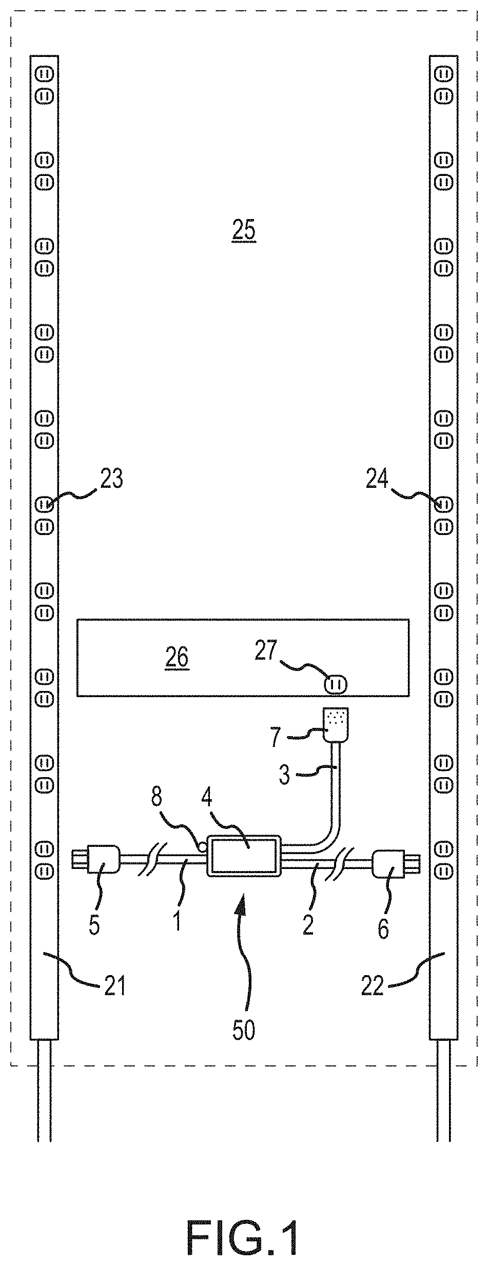
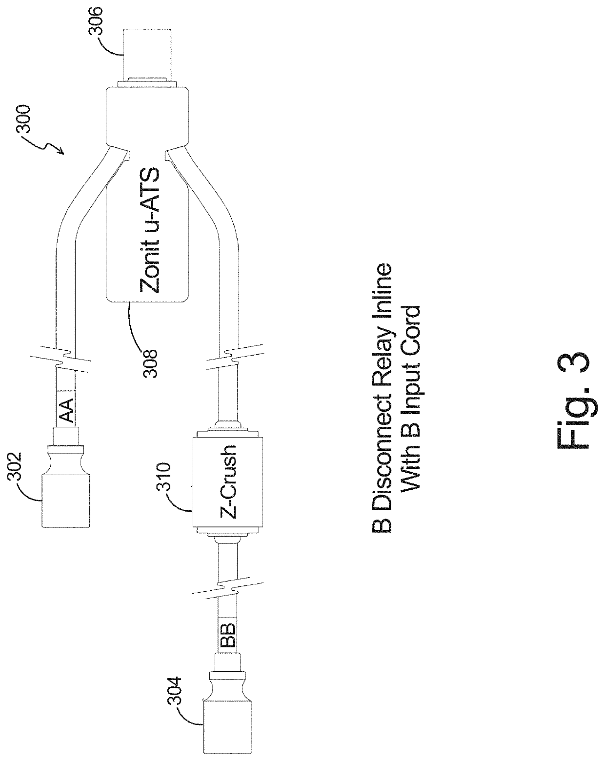
[0047]In one instantiation, in connection with a power cord associated with an ATS, the power surge circuit of the present invention can be implemented in a very small form factor in-line. This has a number of advantages that are detailed below. A point to note is that depending on the design of a given ATS unit, the in-line power surge circuit can be put on the output or one or both power inputs of the ATS unit. This is because an ATS that is designed and / or has been set to use the “A” side as the preferred and primary power source would only need the ...


PUM


Abstract

A system is provided for suppressing transient currents in electrical circuits to prevent damage to switching devices such as relays and / or solid-state switching devices. An associated automatic transfer switch (ATS) system (300) includes a primary power cord terminating in cord cap (302) for receiving power from a primary power source and a secondary power cord terminating in cord cap (304) for receiving power from a secondary power source. The system (300) further includes an output (306) for connecting to an output load such as a piece of electronic equipment. The output (306) may be a female outlet such that the system (300) can be directly connected to a male power port of a piece of equipment. The system (300) further includes a micro-ATS module (308) operative to sense a power outage or degradation of signal quality for the power signal of at least the primary power source and, in response, to switch the power supply from the primary source to the secondary power source. A surge suppression circuit (310) is interposed in the secondary power cord between the module (308) and the cord cap (304).

Description

CROSS-REFERENCES[0001]This application claims priority from provisional U.S. Patent Application No. 62 / 817,456 entitled, “RELAY CONDITIONING AND POWER SURGE CONTROL,” filed Mar. 12, 2019 (the “Parent Application”) and claims priority from the Parent Application to the maximum extent permissible under applicable laws and regulations. The Parent Application is incorporated by reference herein in its entirety.INCORPORATED DOCUMENTS[0002]The following applications (hereinafter “incorporated documents”) are incorporated by reference herein in their entireties:[0003]1) U.S. Provisional Patent Application No. 61 / 372,752, filed Feb. 26, 2013, entitled “HIGHLY PARALLEL REDUNDANT POWER DISTRIBUTION METHODS;”[0004]2) U.S. Patent Application Publication No. US-2012 / 0181869-A1, published on Jul. 19, 2012, entitled, “PARALLEL REDUNDANT POWER DISTRIBUTION,” U.S. patent application Ser. No. 13 / 208,333, (“the '333 Application”) filed on Aug. 11, 2011, entitled, “PARALLEL REDUNDANT POWER DISTRIBUTION...

Claims


Application Information

Patent Timeline
Patent Type & Authority Applications(United States)
IPC IPC(8): H01R29/00H02J9/06H01R25/00H01R13/703
CPCH01R29/00H02J9/06H01H2300/018H01R13/7038H01R25/003H02H9/002H01H1/5866
Inventor PACHOUD, WILLIAMCHAPEL, STEVE
Owner ZONIT STRUCTURED SOLUTIONS LLC
Why Eureka
Try Eureka