Devices and methods for conveying and controlling light beams for lensless endo-microscopic imagery

a technology of endoscope and light beam, which is applied in the field of devices and methods for transporting and controlling light beams, can solve the problems of restricting the application of non-linear imaging, and the inability to build a miniature microscope that would comprise a light source, a focusing optic and a camera at the distal end (i.e. located at the end of the fibre, on the sample side) of a medical endoscop

Active Publication Date: 2021-01-21
CENT NAT DE LA RECHERCHE SCI +2
View PDF0 Cites 3 Cited by
  • Summary
  • Abstract
  • Description
  • Claims
  • Application Information

AI Technical Summary

Benefits of technology

[0046]According to one or more exemplary embodiments, the purpose of applying the phase shift to each of the elementary beams is to impart a determined phase function to the distal extremity of the multimode optical fibre section in order to form a convergent illumination beam at a given distance from an output facet of the multimode optical fibre section, enabling fo

Problems solved by technology

Indeed, building a miniature microscope that would comprise a light source, a focusing optic and a camera at the distal end (i.e. located at the end of the fibre, on the sample side) of a medical endoscope is not conceivable owing to the overall dimensions of the

Method used


Image

  • Devices and methods for conveying and controlling light beams for lensless endo-microscopic imagery
  • Devices and methods for conveying and controlling light beams for lensless endo-microscopic imagery
  • Devices and methods for conveying and controlling light beams for lensless endo-microscopic imagery

Examples


Embodiment Construction

[0062]The same references are used to designate identical elements in the figures.

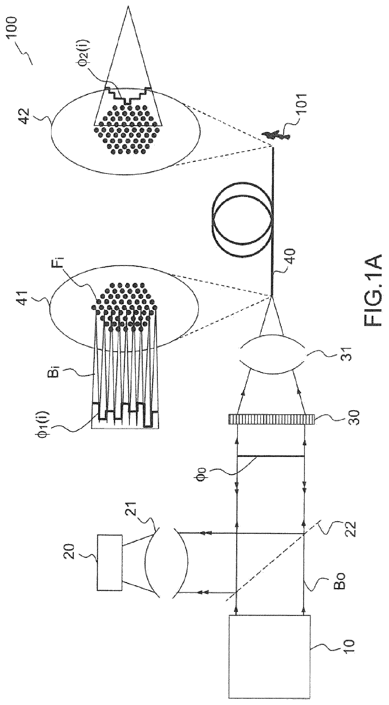
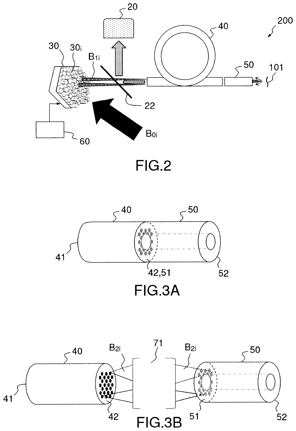
[0063]FIG. 2 illustrates diagrammatically an example of a “lensless” endo-microscopic imaging system 200 with a device for transporting and controlling light beams according to the present description, adapted for imaging an object bearing the reference 101 in FIG. 2.

[0064]The endo-microscopic imaging system 200 comprises a light source (not illustrated in FIG. 2) adapted for emitting light beams B0i, wherein the light beams may include light pulses in the case of application to non-linear imaging. Thus, the light source comprises for example a laser source and, if necessary, an optical system for enlargement and collimation of the light beams emitted.

[0065]The endo-microscopic imaging system 200 further comprises a device for transporting and controlling the light beams emitted by said light source in order to illuminate the object 101 according to a selected intensity figures, for example a focal poi...


PUM


Abstract

According to one aspect, the invention relates to a device for transporting and controlling light beams for endo-microscopic imaging without a lens on the distal side comprising a single-mode optical fibre bundle (40) on the distal side, wherein each single-mode optical fibre is intended to receive an elementary light source and to emit a light beam at a distal end; a single-mode optical fibre section (50) arranged at the distal end of the optical fibre bundle and intended to receive the light beams emitted by the single-mode optical fibres of the optical fibre bundle; an optical phase control device arranged on the side of the proximal end of the single-mode optical fibres. The optical phase control device comprises at least one spatial light modulator (30) adapted to apply a phase shift to each of the elementary beams and control means (60) for controlling the spatial light modulator allowing application of a phase shift to each of the elementary beams to form an illumination beam with a determined phase function at the distal end of the multimode optical fibre section (50).

Description

STATE OF THE ARTTechnical Field of the Invention[0001]The present invention relates to devices and methods for transporting and controlling light beams for so-called “lensless” endo-microscopic imaging in addition to lensless endo-microscopic imaging systems and methods. It applies in particular to endoscopic exploration of organs in a living being, either human or animal.State of the Art[0002]Developments in endo-microscopic imaging call for use of opto-mechanical fibre devices having specific characteristics compared to free-space imaging systems.[0003]Indeed, building a miniature microscope that would comprise a light source, a focusing optic and a camera at the distal end (i.e. located at the end of the fibre, on the sample side) of a medical endoscope is not conceivable owing to the overall dimensions of the entire components. Consequently, solutions are sought that allow performance of imaging at the end of the optical fibre while limiting the overall dimensions at the distal ...

Claims


Application Information

Patent Timeline
IPC IPC(8): G02B23/24G02B6/02
CPCG02B23/2469A61B1/07G02B6/02042G02B23/2423G02B27/0087A61B1/00167A61B1/0017A61B1/00172
Inventor RIGNEAULT, HERVÉANDRESEN, ESBEN RAVNSIVANKUTTY, SIDDARTH
Owner CENT NAT DE LA RECHERCHE SCI
Why Eureka
Try Eureka