Ceramic composite, light source apparatus, and projector
- Summary
- Abstract
- Description
- Claims
- Application Information
AI Technical Summary
Benefits of technology
Problems solved by technology
Method used
Image
Examples
first embodiment
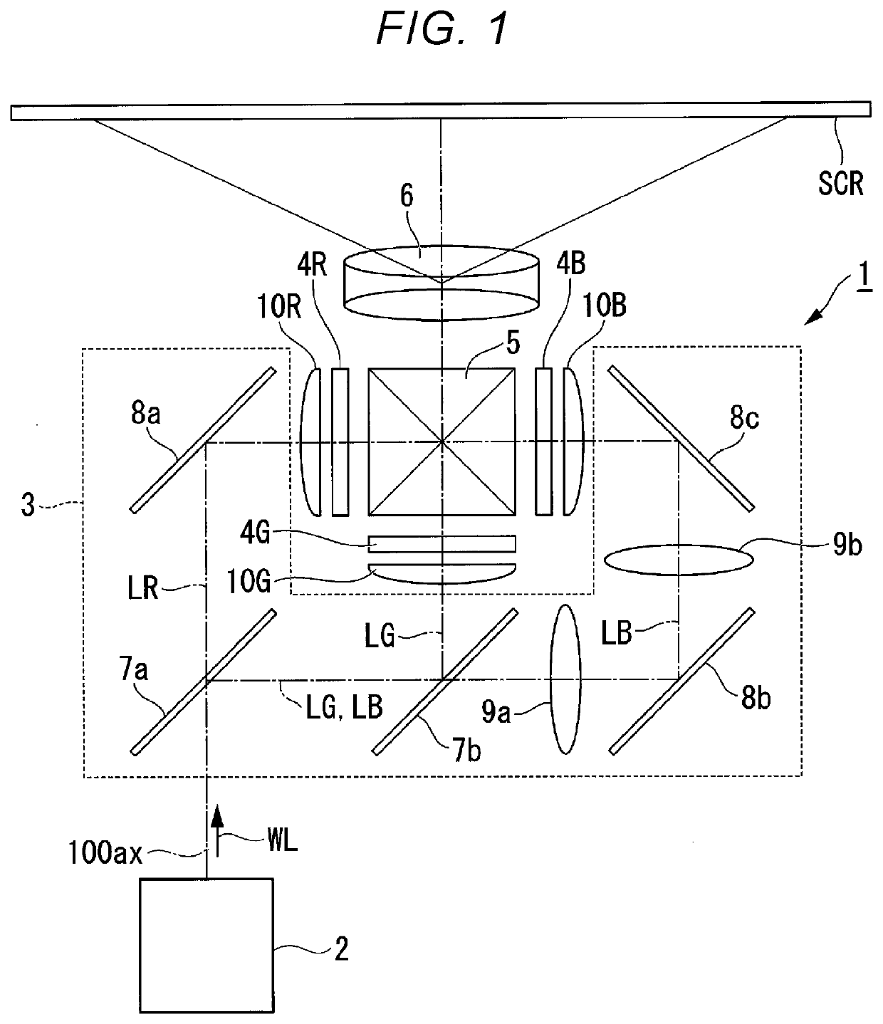
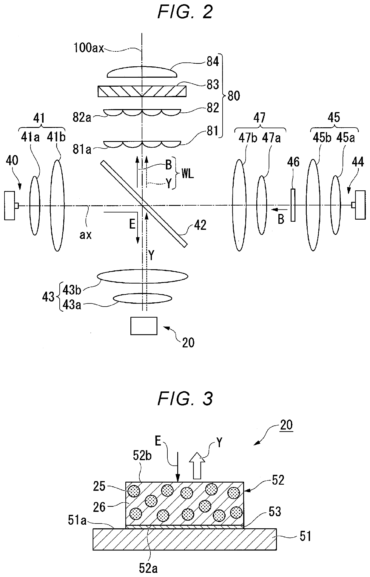
[0027]FIG. 1 shows a schematic configuration of a projector according to a first embodiment. FIG. 2 shows a schematic configuration of a light source apparatus.
[0028]A projector 1 according to the present embodiment is a projection-type image display apparatus that displays video images on a screen SCR, as shown in FIG. 1. The projector 1 includes a light source apparatus 2, a color separation system 3, a light modulator 4R, a light modulator 4G, a light modulator 4B, a light combining system 5, and a projection optical apparatus 6.
[0029]The light source apparatus 2 outputs white illumination light WL toward the color separation system 3.
[0030]The color separation system 3 separates the illumination light WL outputted from the light source apparatus 2 into red light LR, green light LG, and blue light LB. The color separation system 3 includes a first dichroic mirror 7a, a second dichroic mirror 7b, a first total reflection mirror 8a, a second total reflection mirror 8b, a third tota...
second embodiment
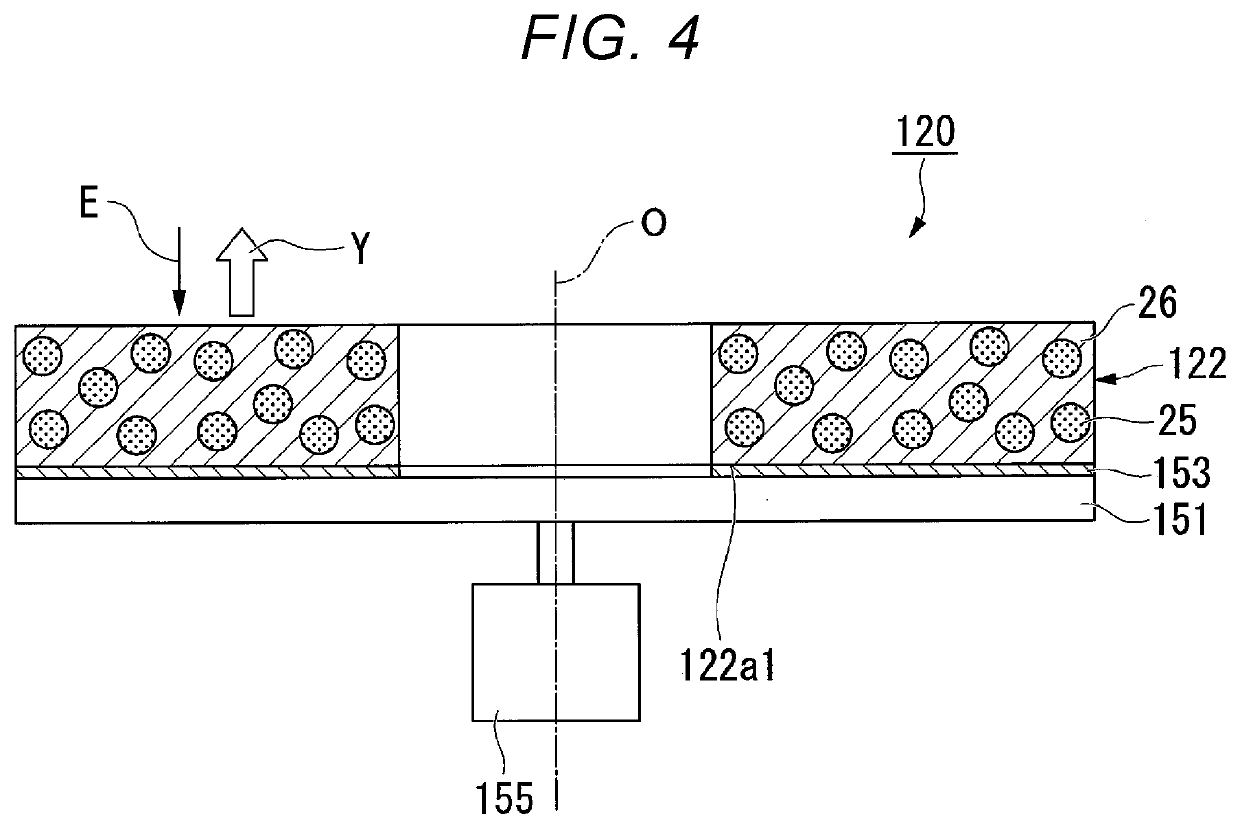
[0074]A second embodiment of the present disclosure will be described below with reference to FIG. 4.
[0075]A schematic configuration of a projector according to the second embodiment is the same as that in the first embodiment, and the wavelength converter in the light source apparatus differs in terms of configuration from the wavelength converter of the first embodiment. Therefore, the configuration of the wavelength converter will be described and other configurations will not be described below.
[0076]FIG. 4 is a cross-sectional view showing the configurations of key parts of the wavelength converter of the present embodiment. A wavelength converter 120 of the present embodiment includes a substrate 151, a ceramic phosphor 122, a reflection layer 153, and a motor 155, as shown in FIG. 4. The wavelength converter 120 of the present embodiment is a rotary-wheel-type wavelength converter so configured that a light incident position where the excitation light E is incident on the cer...
third embodiment
[0083]A third embodiment of the present disclosure will be described below with reference to FIG. 5.
[0084]A schematic configuration of a projector according to the third embodiment is the same as that in the first embodiment, and the light source apparatus differs in terms of configuration from the light source apparatus according to the first embodiment. Therefore, the configuration of the light source apparatus will be described and other configurations will not be described below.
[0085]FIG. 5 shows a schematic configuration of a light source apparatus 2A.
[0086]The light source apparatus 2A includes an excitation light source unit 10, an afocal system 11, a homogenizer system 12, a light convergence system 13, a wavelength converter 220, a pickup system 30, and a uniform illumination system 80, as shown in FIG. 5.
[0087]The excitation light source unit 10 is formed of a plurality of semiconductor lasers 10a, which each output blue excitation light E formed of laser light and a plur...
PUM
 Abstract
Description
Claims
Application Information
 - R&D Engineer
- R&D Manager
- IP Professional
- Industry Leading Data Capabilities
- Powerful AI technology
- Patent DNA Extraction
Browse by: Latest US Patents, China's latest patents, Technical Efficacy Thesaurus, Application Domain, Technology Topic, Popular Technical Reports.
© 2024 PatSnap. All rights reserved.Legal|Privacy policy|Modern Slavery Act Transparency Statement|Sitemap|About US| Contact US: help@patsnap.com


