
Floating platform for maritime surveillance

a floating platform and surveillance technology, applied in the direction of instruments, vessel construction, and reradiation, can solve the problems of limited capacity for carrying surveillance sensor equipment, small surveillance radius, and high cos

Active Publication Date: 2021-02-11
ETME PEPPAS KAI SYNERGATES EE
View PDF0 Cites 5 Cited by
  • Summary
  • Abstract
  • Description
  • Claims
  • Application Information

AI Technical Summary

Benefits of technology

The invention is a floating platform that can accommodate unmanned vehicles and move from one platform to another. It is designed to maintain a constant range of surveillance, regardless of waves and adverse weather conditions. The platform is unmanned, reducing cost and size, while still maintaining optimal hydrodynamic properties and being autonomous and minimal maintenance. This makes it suitable for offshore surveillance. The technical effects of this invention are improved efficiency and cost-effectiveness of offshore surveillance, with reduced risk to human operators.

Problems solved by technology

In particular, surface or underwater vessels can provide monitoring of a maritime area through periodically moving into the area of interest, however without permanently remaining at a fixed point within it, since they must return to their base at regular intervals and require personnel on board, thereby having a very high cost.
The buoys have a relatively small radius of surveillance due to the limited height and size thereof, are occasionally subjected to undesirable movements and inclinations, have a limited capacity of carrying surveillance sensor equipment due to low displacement, limited power generation and proximity to sea level thereof.
They cannot carry unmanned vehicles and the surveillance range thereof is limited due to the low level at which surveillance sensors are mounted particularly in view of proximally apparent earth curvature.
Moreover, they cannot provide underwater surveillance and have very high operational costs.
Satellites have a very high cost, remotely monitor an area subject to surveillance mostly in a passive way since they do not have radiation emitters due to their limited capacity of power generation, thereby being deficient in locating non-radiating objects.
Furthermore satellites used for maritime surveillance cannot provide supervision of the underwater space, whilst they cannot maintain a stable position above a region of interest, but have to constantly move, thereby leaving gaps wherein surveillance is not performed.
Unmanned vehicles also move and do not maintain a fixed location, thereby being incapable of providing continuous surveillance of a specifically defined area of interest, whilst they further have to return to their base for repair and maintenance and in this respect surveillance has to be interrupted.
Unmanned vehicles are also incapable of monitoring sea surface in a specified area of interest simultaneously with the aerial and underwater area pertaining to such specified area.
In conclusion, means and methods of surveillance of the prior art cannot simultaneously provide surveillance of specified maritime areas (such as underwater infrastructure, coastal infrastructures, illegal immigration maritime zones, maritime piracy zones, illegal maritime fishing areas, maritime zones wherein navigation is banned etc.) including the aerial and underwater area pertaining to such specified maritime areas in a continuous uninterrupted mode, being autonomous in respect of energy production, capable of containing unmanned vehicles, at low cost and without the need for frequent maintenance.

Method used


Image

  • Floating platform for maritime surveillance
  • Floating platform for maritime surveillance
  • Floating platform for maritime surveillance

Examples


Embodiment Construction

[0026]The invention will be hereinafter described by reference to the illustrative embodiments presented in the accompanying drawings.

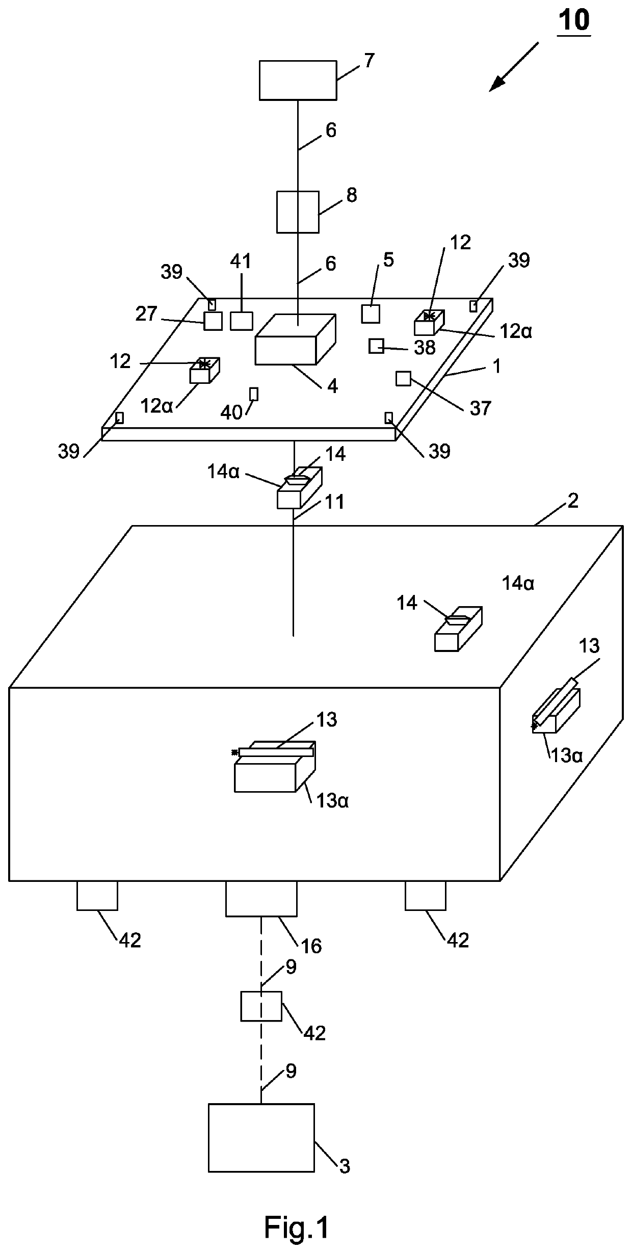
[0027]FIG. 1 shows an embodiment of a floating platform of the invention for the surveillance of a maritime zone. The floating platform is unmanned, autonomous and is adapted to maintain a fixed location, thereby being adapted to provide a continuous surveillance of a sea surface area and of the aerial and underwater space pertaining to this sea surface area of the maritime zone under surveillance. Continuous surveillance is being achieved since the floating platform does not need to be removed for refueling or maintenance and it may remain within the maritime zone under surveillance constantly for the entire duration of operation thereof.

[0028]The floating platform of FIG. 1 comprises a deck 1 maintained well above sea level 60 at any circumstances, a system of floaters 2 and anchorages 3 lying onto the seabed and maintaining the system of floaters 2...


PUM


Abstract

An unmanned, autonomous, self-sustaining and self-repairable floating platform which is positioned at a fixed location within the sea, capable of constantly monitoring, without having to be removed, a specific maritime zone including a sea surface area and the aerial and underwater space pertaining to this sea surface area, the platform comprising telecommunication means adapted to exchange surveillance related information with a Command, Communication and Control center. The platform comprises a deck maintained well above sea surface through a connecting member with an underlying, fully or partially submerged, system of floaters and is equipped with a variety of sensors and surveillance systems such as radar, Li-dar, sonar, electromagnetic, unmanned vehicles (UAVs, UUVs and USVs), active and passive self-protection systems as well as research and rescue equipment. A mast having a substantial height (usually 40-50 m) and equipped with appropriate surveillance devices is mounted and ex-tends vertically upwardly the deck.

Description

THE FIELD OF THE ART[0001]The invention relates to an unmanned, autonomous floating platform comprising a deck supported by a system of floaters anchored at specific fixed points within the seabed, such floating platform being adapted to provide, without necessitating removal thereof, continuous and persistent surveillance of a specific maritime area including the sea surface, as well as the aerial and underwater space above and below the sea surface, the floating platform being provided with sensors and surveillance systems such as radars, lidars, sonars, electro-optics and unmanned vehicles including unmanned surface vehicles (USVs), unmanned aerial vehicles (UAVs) and unmanned underwater vehicles (UUVs), wherein the floating platform of the invention is being adapted to continuously transfer information of the surveillance activity thereof to a command, communication and control center.THE PRIOR ART[0002]Various maritime surveillance devices are known in the prior art, including ...

Claims


Application Information

Patent Timeline
Patent Type & Authority Applications(United States)
IPC IPC(8): B63B35/44G01S13/86G01S17/88G01S15/88
CPCB63B35/44G01S13/862B63B2022/006G01S17/88G01S15/88G01S13/865G01S7/003G01S13/87G01S13/917G01S2013/0227B63B2035/007B63B2035/4433Y02E10/727Y02E10/72B63B1/107B63B21/502F03B13/12F03D13/25
Inventor PEPPAS, ANTONIOS
Owner ETME PEPPAS KAI SYNERGATES EE
Learn More