Interface electronic device for reading an output signal and for controlling and conditioning a three-electrodes amperometric sensor

a technology of amperometric sensor and interface electronic device, which is applied in the field of devices, can solve the problems of high energy consumption, unstable voltage on the working electrode, oscillation and instability of the circuit,

Pending Publication Date: 2021-02-11
DISTRETTO TECHCO SICILIA MICRO E NANO SISTEMI S C A R L
View PDF0 Cites 1 Cited by
  • Summary
  • Abstract
  • Description
  • Claims
  • Application Information

AI Technical Summary

Problems solved by technology

For example, it requires a double power supply and suffers from a high energy consumption due to the presence of several (at least two) operational amplifiers.
Furthermore, the voltage on the working electrode WE is not stable due to the further resistance RL, placed between the working electrode WE and the inverting input of the operational amplifier U1.
These circuits, however, may suffer from the further drawback of having a high equivalent input impedance, measured by the collector electrode CE, which causes oscillations and instability of the circui...

Method used


Image

  • Interface electronic device for reading an output signal and for  controlling and conditioning a three-electrodes amperometric sensor
  • Interface electronic device for reading an output signal and for  controlling and conditioning a three-electrodes amperometric sensor
  • Interface electronic device for reading an output signal and for  controlling and conditioning a three-electrodes amperometric sensor

Examples


Embodiment Construction

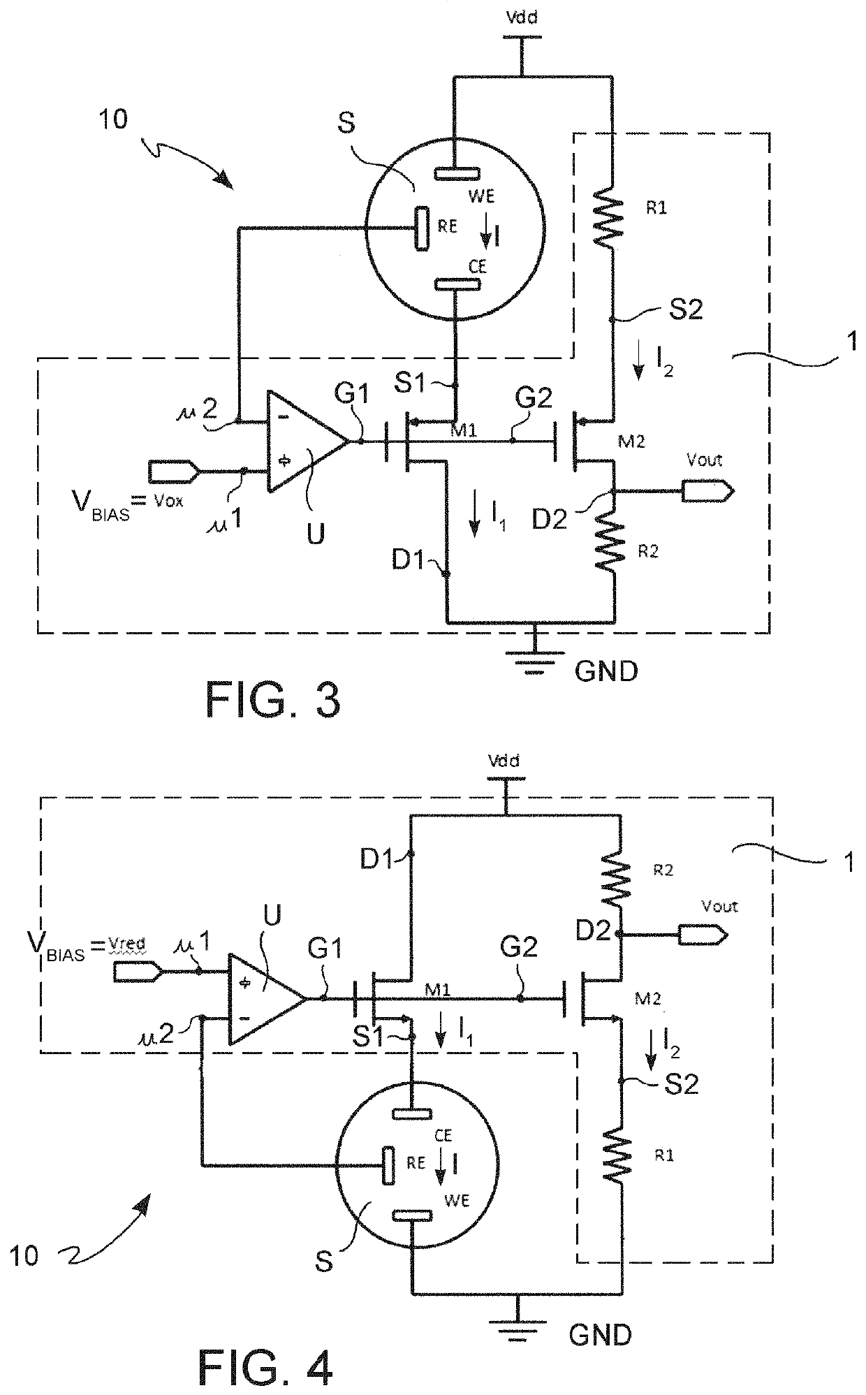
[0033]With reference to FIGS. 3 and 4, an electronic device 1 for reading an output signal and controlling a three-electrode electrochemical amperometric sensor S is now described.

[0034]In FIGS. 3 and 4, the device 1 is enclosed by a dashed line, and interacts with the larger system for measuring an electrolyte concentration 10, which also comprises, in addition to the device 1, also the sensor S which is controlled and conditioned by the device 1.

[0035]In particular, but not limited to, the definition of “electronic device” applies herein to a circuit structure capable of reading the output signal and controlling the aforesaid amperometric sensor.

[0036]It should be noted that such a circuit structure may be implemented by means of the most diverse implementation options, in terms of integrated or discrete technology, and in terms of partition of the device components (which may be non-integrated, or integrated with each other, or partly integrated with the sensor and partly integra...


PUM


Abstract

There is described an electronic interface device (1) for reading an output signal and controlling and conditioning a three-electrode amperometric sensor (S). The device (1) may be used with a sensor having an electro-chemical cell comprising a reference electrode (RE) configured to supply a constant cell electric potential to the electrochemical cell; a working electrode (WE) at which oxidation or reduction reactions occur, connectable to a first reference voltage; and a collector electrode (CE) configured to deliver or receive electric charge carriers. In the electro-chemical cell, a cell impedance (Zcw) is always present between the working electrode (WE) and the collector electrode (CE).
The device (1) comprises an operational amplifier (U), having a non-inverting input (u1), adapted to receive a biasing electric potential (VBIAS) depending on the type of electrochemical reaction of the sensor, and an inverting input (u2) connectable to the reference electrode (RE) of the sensor. The operational amplifier is adapted to operate in a feedback configuration to supply the reference electrode (RE) with the aforementioned constant cell electric potential on the basis of the biasing electric potential (VBIAS).
The device (1) further comprises a first MOS transistor (M1), having a first MOS gate terminal (G1) connected to the output of the operational amplifier (U), a first MOS drain terminal (D1), connectable to a second reference voltage, and a first MOS source terminal (S1), connectable to the collector electrode CE of the sensor (S) to receive or supply a first MOS transistor channel current (I1) representative of (for example equal to) the cell current (I) which is generated in the amperometric sensor (S).
The device (1) further comprises a second MOS transistor (M2) having a second MOS gate terminal (G2) connected to the output of the operational amplifier (U) and to the aforementioned first MOS gate terminal (G1), a second MOS source terminal (S2), connectable to the first reference voltage by means of a first resistor (R1), and a second MOS drain terminal (D2), connectable to the second reference voltage (for example, through a resistor R2 which allows the reading of a voltage proportional to the current).
The value of the first resistor (R1) is lower than the cell impedance (Zcw) so that the second MOS transistor channel current (I2) depends on the first MOS transistor channel current (I1), representative of the cell current (I) of the sensor, through a nonlinear gain dependent at least on the value of the first resistor (R1).
The second MOS transistor (M2) is of the same type as the first MOS transistor (M1).
Also described is a method for reading an output and control signal of a three-electrode amperometric sensor, carried out by the aforementioned device.

Description

TECHNOLOGICAL BACKGROUND OF THE INVENTIONApplication Field[0001]The present invention generally relates to the technical field of electronic devices for reading signals from sensors.[0002]In particular, the invention relates to a device, a circuit diagram and a method for reading an output signal and controlling an electro-chemical amperometric sensor.Description of the Prior Art[0003]It is known to use electro-chemical amperometric sensors, or three-electrode sensors, capable of determining the concentration of a chemical substance (analyte) by measuring the current which is determined in the electrolytic cell following oxidation or reduction reactions which take place at the electrodes.[0004]More specifically, as shown in FIG. 1A, the electro-chemical cell EC comprises a working electrode WE, at which the oxidation or reduction reaction takes place, maintained at a stable and known potential with respect to a reference electrode RE, and a collector electrode CE adapted to collect ...

Claims


Application Information

Patent Timeline
IPC IPC(8): G01N27/327
CPCG01N27/3273G01N27/3277G01N27/4148
Inventor MAIRA, GIOVANNIOCCHIPINTI, LUIGIPIGNATARO, BRUNO GIUSEPPEVINCIGUERRA, VINCENZO
Owner DISTRETTO TECHCO SICILIA MICRO E NANO SISTEMI S C A R L
Why Eureka
Try Eureka