Carbon negative clean fuel production system

a clean fuel and production system technology, applied in the field of energy harvesting, can solve the problems of increasing difficulty in finding new energy sources, limited studies of mineral content, temperature variations, etc., and achieve the effect of reducing the concentration of carbon dioxide in the atmospheric air

Active Publication Date: 2021-02-25
LOWRY INHERITORS TRUST
View PDF0 Cites 1 Cited by
  • Summary
  • Abstract
  • Description
  • Claims
  • Application Information

AI Technical Summary

Benefits of technology

[0039]a carbon removal system, which is configured to use the electric energy generated by the heat driven electric generator to pump in atmospheric air, and to produce formic acid from carbon dioxide in the atmospheric air, thereby reducing a concentration of carbon dioxide in the atmospheric air.

Problems solved by technology

The difficulty of accessing these vents has limited studies as to their mineral contents, temperature variations, surrounding biology and other factors.
It is becoming increasingly difficult to find new energy sources and existing sources are insufficient to meet our long-term needs creating the ever-increasing use of fossil fuels thereby threatening the very existence of life on this planet through global warming.
Some properties of silane, disilane, and trisilane make them difficult to use as a gasoline replacement in cars, but they are suitable for highly controllable environments like electricity generating power plants, trains and ships.

Method used


Image

  • Carbon negative clean fuel production system
  • Carbon negative clean fuel production system
  • Carbon negative clean fuel production system

Examples


Embodiment Construction

[0053]Before describing the invention in detail, it should be observed that the present invention resides primarily in a novel and non-obvious combination of elements and process steps. So as not to obscure the disclosure with details that will readily be apparent to those skilled in the art, certain conventional elements and steps have been presented with lesser detail, while the drawings and specification describe in greater detail other elements and steps pertinent to understanding the invention.

[0054]The following embodiments are not intended to define limits as to the structure or method of the invention, but only to provide exemplary constructions. The embodiments are permissive rather than mandatory and illustrative rather than exhaustive.

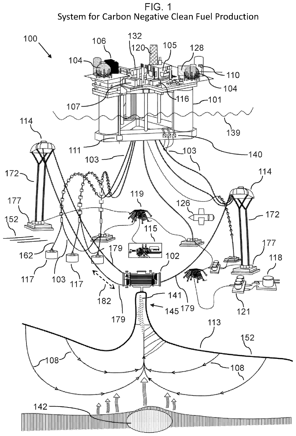
[0055]In the following, we describe the structure of an embodiment of a carbon negative clean fuel production system 100 with reference to FIG. 1, in such manner that like reference numerals refer to like components throughout; a convention ...


PUM

PropertyMeasurementUnit
temperatureaaaaaaaaaa
pressureaaaaaaaaaa
temperatureaaaaaaaaaa

Abstract

A carbon negative clean fuel production system includes: a main platform; a heat collection device for capturing heat from a hydrothermal emissions from a hydrothermal vent on a floor of an ocean; a heat driven electric generator; a heat distribution system including a heat absorbing material and a heat transporting pipe; anchor platforms tethered to the main platform; a mineral separator; a seawater filtration unit; a water splitting device; a sand refinery machine; a carbon removal system; and a chemical production system for producing hydrides, halides and silane. Also disclosed is a method for carbon negative clean fuel production, including: capturing heat; producing electric energy; separating minerals; filtering seawater; splitting water; refining sand; removing carbon dioxide; and producing hydrides, halides, and silane.

Description

CROSS-REFERENCE TO RELATED APPLICATIONS[0001]N / A.FIELD OF THE INVENTION[0002]The present invention relates generally to energy harvesting, and more particularly, to harvesting energy from subsea hydrothermal vents, for conversion into alternative fuel stores.BACKGROUND OF THE INVENTION[0003]Hydrothermal vents are fissures in the seafloor from which heated water issues. Hydrothermal vents are found in areas associated with movement of tectonic plates and ocean basin hotspots. These vents are located on the plate expansion zones known as the mid-ocean ridges and on the plate subduction zones known as the ring of fire. The number of hydrothermal vents is unknown, but experts have recently placed the number as high as 10 million.[0004]The Woods Hole Institute keeps a database of known hydrothermal vents including their GPS position, their depth, active status and other known data. For example, the Alarcon rise vent field is listed in the database at a latitude of 23.3553 and longitude o...

Claims


Application Information

Patent Timeline
Patent Type & Authority Applications(United States)
IPC IPC(8): F03G7/04B01D61/02C02F1/44C02F1/48C01B33/025B01D53/32C02F1/52C25B1/04C25B9/06C25B3/04F02G1/055
CPCF03G7/04B01D61/025C02F1/441C02F1/48C01B33/025C02F2103/08C02F1/52C25B1/04C25B9/06C25B3/04F02G1/055B01D53/326B01D63/025C02F1/025C02F1/461C02F9/00C02F2201/008C02F2303/10Y02E60/36Y02W10/30C02F2201/001C25B3/25C25B9/17F02G2254/00F02G2280/20
Inventor LOWRY, SCOTT D.
Owner LOWRY INHERITORS TRUST
Why Eureka
Try Eureka