Closed loop energy production from producing geothermal wells

a geothermal well and closed-loop technology, applied in indirect heat exchangers, machines/engines, lighting and heating apparatus, etc., can solve the problems of high cost of hydrothermal well drilling success, high cost of hydrothermal resources, and high cost of locating appropriate hydrothermal resources, so as to reduce the potential of steam condensation

Active Publication Date: 2021-03-04
GREENFIRE ENERGY
View PDF0 Cites 24 Cited by
  • Summary
  • Abstract
  • Description
  • Claims
  • Application Information

AI Technical Summary

Benefits of technology

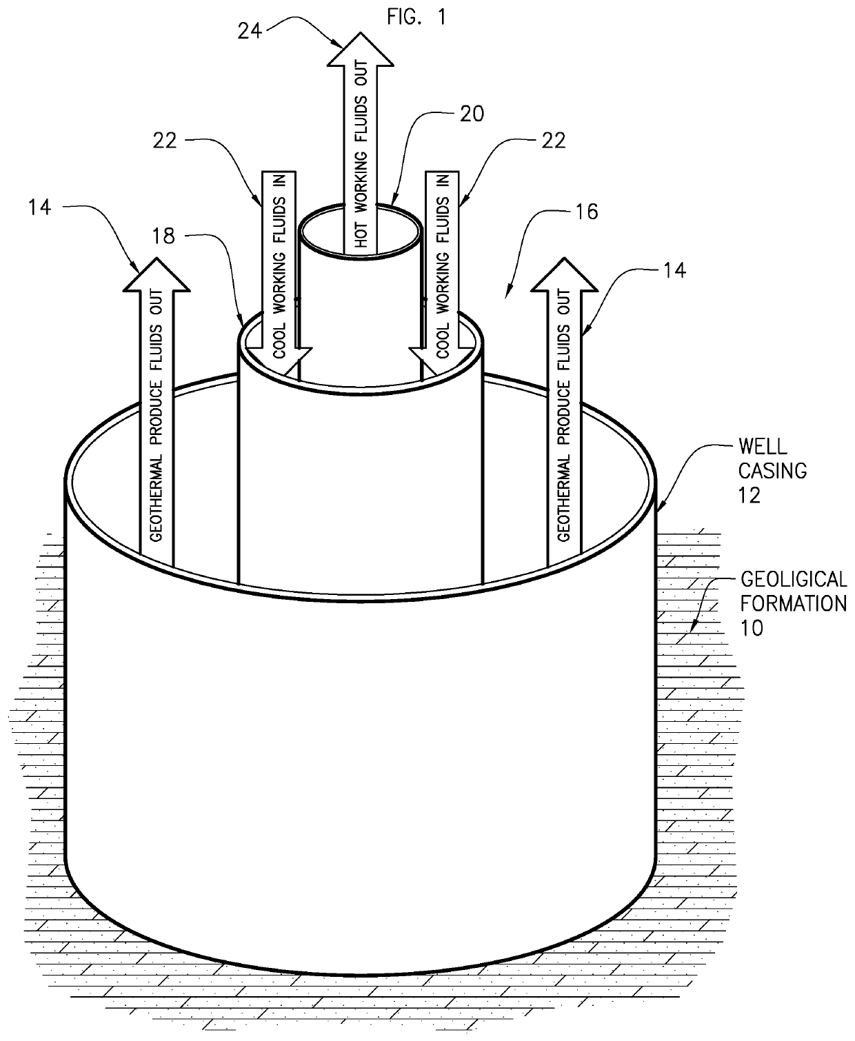
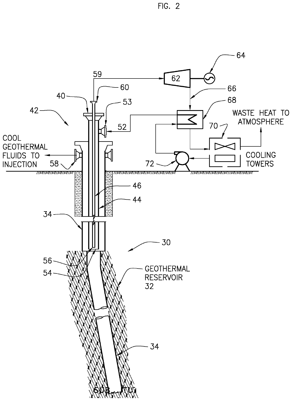
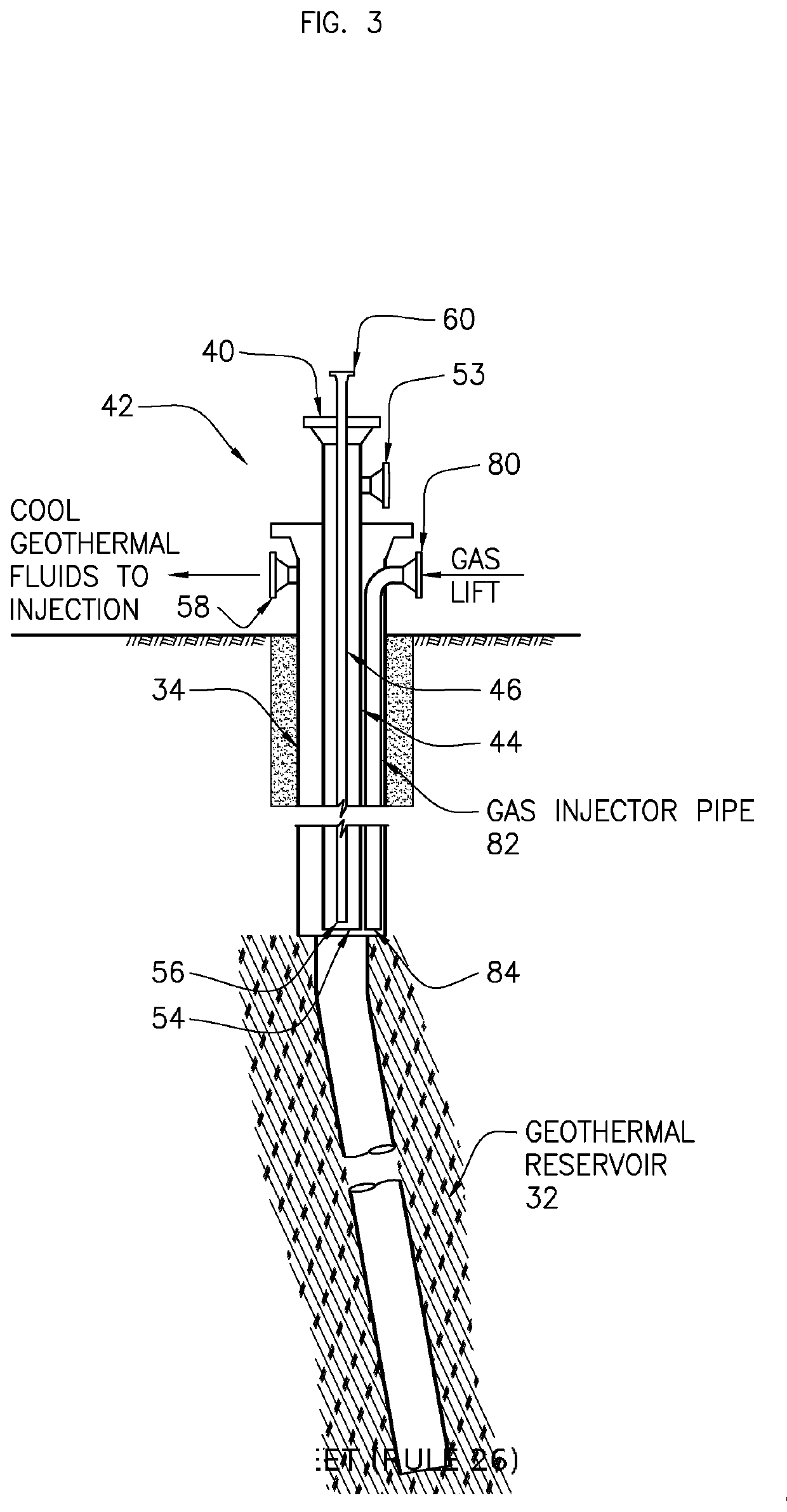
[0020]In another aspect, embodiments disclosed herein relate to a system for producing working fluid and generating thermal or electrical power from a geothermal reservoir containing steam. The system may include a heat exchanger disposed within the outer production conduit comprised of a lined well or hole open to the reservoir, the heat exchanger comprising an outer heat exchange conduit and an inner conduit. A working fluid circulation system may be used for circulating a working fluid (a) through the outer heat exchange conduit and into the inner conduit or (b) through the inner heat exchange conduit and into the outer heat exchange conduit. A measurement and control system may provide for controlling the rate of flow of the working fluid in the heat exchanger configured to result in steam condensing into water at or near the surface of the outer conduit of the heat exchanger causing a significant density difference resulting in the condensed steam flowing deeper into the reservoir, thereby causing steam to flow from deeper in the geothermal resource towards the conduit adding advection heating to the conduction heating. In some embodiments, this flow of condensed steam to deeper in the reservoir and adding advection heating will set up a convection loop of water circulating up in the resource and down in the production conduit surrounding the heat exchanger. A system of one or more plugs or other barriers may be disposed in the annulus between the well and the outer conduit of the heat exchanger configured to prevent steam from rising up the annulus around the outer conduit of the heat exchanger rather than condensing into water at or near the surface of the outer conduit of the heat exchanger below the barriers. Further, an energy utilization or conversion system for using or converting energy contained in the heated working fluid recovered from the heat exchanger at the surface for thermal or electrical power. In some embodiments, a system of gas, insulation or other fill material may be installed between the casing of the well or open borehole and outer conduit of the heat exchanger above the plugs of other barriers. In some embodiments, a tube may be inserted between the casing of the well or open borehole and outer conduit of the heat exchanger and pass through such plugs or other barriers to transport any collected NCGs to the surface.
[0021]In another aspect, embodiments herein relate to a process for producing working fluid and generating thermal or electrical power from a geothermal reservoir containing steam. The process may include disposing a heat exchanger within the outer production conduit comprised of a lined well or hole open to the reservoir, the heat exchanger comprising an outer heat exchange conduit and an inner conduit. A working fluid may be circulated through the outer heat exchange conduit and into the inner conduit or vice versa. The rate of flow of the working fluid in the heat exchanger may be controlled such that steam condenses into water at the surface of the outer conduit of the heat exchanger, causing a significant density difference resulting in the condensed steam flowing deeper into the reservoir causing steam to flow from deeper in the geothermal resource towards the conduit adding advection heating to the conduction heating. One or more plugs or other barriers in the annulus may be disposed between the well and the outer conduit of the heat exchanger, thereby preventing steam from rising up the annulus around the outer conduit of the heat exchanger rather than condensing into water at the surface of the outer conduit of the heat exchanger below the barriers. The process may also include using or converting energy contained in the heated working fluid recovered from the heat exchanger at the surface for thermal or electrical power. In some embodiments, the process may also include installing gas, insulation or other fill material between the casing of the well or open borehole and outer conduit of the heat exchanger above the plugs of other barriers.
[0022]In yet another aspect, embodiments herein relate to a system for producing fluid and generating power or electricity or other conversion technology from a geothermal reservoir containing dry steam. The system may include a heat exchanger disposed within the outer production conduit, and a cased or open hole into the reservoir. The heat exchanger may include an outer heat exchange conduit and an inner conduit. A working fluid circulation system may be provided for circulating a working fluid through the outer heat exchange conduit and into the inner conduit, and a controller may be configured to control a pump rate that results in steam condensing into water at the surface of the outer heat exchanger conduit causing a significant density difference resulting in the condensed steam flowing deeper into the reservoir causing steam to flow towards the conduit. Further, an energy conversion system may be provided for converting energy, contained in the heated working fluid recovered from the inner conduit, to thermal power or electricity. A gas or other fill material may be disposed between the casing and outer conduit to reduce the potential of steam condensing and becoming corrosive due to the reactions of chloride or other chemicals in the superheated steam with condensed steam resulting in HCl or other corrosive chemicals.

Problems solved by technology

Power from solar and wind is intermittent and poses problems for the electrical grid, which require expensive storage solutions to address.
Nevertheless, geothermal power is underutilized.
A principal reason for this underutilization is the high expense of locating appropriate hydrothermal resources and drilling successful hydrothermal wells.
Many wells drilled into such resources are only marginally successful, have too much non-condensable gases, are simply not powerful enough to be connected to power conversion systems, or, if initially successful, they lose substantial power generation capacity over time.
Some limitations arise from using the above methods.
As most wells exhibit a monotonically-decreasing relationship between pressure and flow, a limitation on the required produced pressure is equally a limitation on the amount of fluid that can be produced.
The lack of sufficient pressure from a geothermal well, or equivalently, a low mass flow at an acceptable pressure, is a severe restriction to producing geothermal power.
A second limitation of the above methods is that as geothermal brine and steam expands in its rise to the surface, it loses pressure and temperature due to expansion.
There is commonly additional heat loss to the surrounding rock as the fluid approaches the surface.
A third limitation of the above methods is that geothermal brine often contains high concentrations of leached chemicals, which can cause corrosion or scale to downstream equipment, requiring expensive maintenance or chemical treatment.
A fourth limitation of the above methods is that geothermal steam and brine will commonly contain non-condensable gases (NCGs).
NCGs cannot be easily separated from the water or steam before producing power, and they often do not contribute significantly to power that is produced.
Further, at significant expense, they must be separated from the water in the condenser after the turbine.
A further limitation of the above methods is that some geothermal resources may be sufficiently hot to produce dry steam, but the steam may not be easily useable to produce power due to corrosive, toxic, or other elements in the steam.

Method used


Image

  • Closed loop energy production from producing geothermal wells
  • Closed loop energy production from producing geothermal wells
  • Closed loop energy production from producing geothermal wells

Examples


Embodiment Construction

[0032]In a geothermal reservoir, the hot fluids are generally under tremendous pressure, the source of this pressure being the rock overburden (lithostatic pressure), the water table (hydrostatic pressure), or some combination of the two. As geothermal fluid comprised of steam and / or brine is produced from a geothermal reservoir via a well, it undergoes a reduction in pressure. Indeed, this pressure difference is what propels the geothermal steam or brine to the surface. Depending on the pressure and the enthalpy of the steam or brine, it may expand or flash to a vapor as it rises up the well. While this does not adversely affect the enthalpy of the produced fluid, it does result in a decreased temperature of the produced mixture of steam and brine. If a heat exchanger only at the surface is used to transfer this heat into a separate working fluid, as is typically used in binary systems, the working fluid cannot be made hotter than the brine and steam temperature at the surface. Thi...


PUM


Abstract

Methods and systems for producing thermal or electrical power from geothermal wells. Power is produced from a working fluid circulating in a closed loop within a geothermal well. Geothermal steam or brine at depth transfers heat at higher temperature than at the surface to the working fluid. The working fluid is then used to produce power directly or indirectly. The geothermal production fluid may be stimulated through use of gas lifting or submersible pumps to assist in bringing such fluids to the surface or through the use blockers to encourage the downhole steam advection and brine recirculation through the resource in a connective loop. The working fluid may be compatible with existing direct heat or power generation equipment; i.e., water for flash plants or hydrocarbons/refrigerants for binary plants.

Description

FIELD OF THE DISCLOSURE[0001]The present invention relates generally to apparatus and methods for recovering energy from geothermal reservoirs. More specifically, the present invention relates to apparatus and methods for increasing the productivity of nonproducing geothermal wells, marginally producing geothermal wells, or even productive geothermal wells.BACKGROUND[0002]As the effects of greenhouse gases become more apparent, more emphasis has been placed on the further development of renewable energy resources. Power from solar and wind is intermittent and poses problems for the electrical grid, which require expensive storage solutions to address. In contrast, power produced from geothermal energy is baseload power that can be flexibly dispatched. Nevertheless, geothermal power is underutilized. A principal reason for this underutilization is the high expense of locating appropriate hydrothermal resources and drilling successful hydrothermal wells. Many wells drilled into such r...

Claims


Application Information

Patent Timeline
Patent Type & Authority Applications(United States)
IPC IPC(8): F01K23/02F24T10/20F28D20/00
CPCF01K23/02F28D20/0052F24T10/20F24T10/00F28D20/00Y02E60/14F24T10/17Y02E10/10F03G4/001F03G4/029F03G4/031F03G7/04F03G7/045
Inventor HIGGINS, BRIAN S.SCHERER, JOSEPH A.HOYER, DAN
Owner GREENFIRE ENERGY
Why Eureka
Try Eureka