Eureka AIR delivers breakthrough ideas for toughest innovation challenges, trusted by R&D personnel around the world.

Integrated circuit and power supply circuit

Active Publication Date: 2021-03-04
FUJI ELECTRIC CO LTD
View PDF0 Cites 0 Cited by
  • Summary
  • Abstract
  • Description
  • Claims
  • Application Information

AI Technical Summary

Benefits of technology

The present patent allows for an integrated circuit that can operate a power supply circuit effectively even when the operating conditions change.

Problems solved by technology

Thus, it is difficult to desirably operate the power supply circuit, for example, when an interruption of the AC voltage, a sudden load change, and / or the like occurs so that an operating condition of the power-factor correction circuit greatly changes.

Method used


Image

  • Integrated circuit and power supply circuit
  • Integrated circuit and power supply circuit
  • Integrated circuit and power supply circuit

Examples


embodiment

Present Embodiment

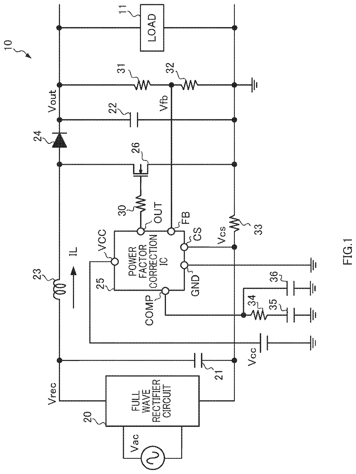
[0026]FIG. 1 is a diagram illustrating a configuration of an AC-DC converter 10 according to one embodiment of the present disclosure. The AC-DC converter 10 is a boost-chopper-type power supply circuit that generates an output voltage Vout at a target level from an AC voltage Vac of a commercial power supply. A load 11 is a DC-DC converter or an electronic device that operates with a direct current voltage, for example.

10>>>

[0027]The AC-DC converter 10 comprises a full wave rectifier circuit 20, capacitors 21, 22, 35, and 36, an inductor 23, a diode 24, a power factor correction IC 25, an NMOS transistor 26, and resistors 30 to 34.

[0028]The full wave rectifier circuit 20 full-wave rectifies the applied predetermined AC voltage Vac, and outputs the result to a capacitor 21 and the inductor 23 as a rectified voltage Vrec. Note that the AC voltage Vac has, for example, a voltage of 100 to 240V and a frequency of 50 to 60 Hz.

[0029]The capacitor 21 smooths the rectifie...


PUM


Abstract

A power supply circuit that generates an output voltage from an AC voltage. The power supply circuit includes a rectifier circuit that rectifies the AC voltage, an inductor receives a rectified voltage from the rectifier circuit, a transistor that controls an inductor current flowing through the inductor, and an integrated circuit that performs switching of the transistor. The integrated circuit includes an error output circuit that outputs an error between a feedback voltage and a reference voltage, a target value generating circuit that generates a target value of the inductor current based on the error, an adjustment circuit that adjusts the target value, first and second comparison circuits that compare the inductor current with a predetermined value and with the target value, respectively, and a drive circuit that turns on the transistor when the inductor current reaches the predetermined value, and turns off the transistor when the inductor current reaches the target value.

Description

CROSS-REFERENCE TO RELATED APPLICATIONS[0001]The present application claims priority pursuant to 35 U.S.C. § 119 from Japanese patent application number 2019-161013, filed on Sep. 4, 2019, the entire disclosure of which is hereby incorporated by reference herein.BACKGROUNDTechnical Field[0002]The present invention relates to an integrated circuit and a power supply circuit.Description of the Related Art[0003]One example of power supply circuit that improves a power factor while generating an output voltage of a target level from an AC voltage is a power-factor correction circuit (for example, Japanese Patent Application Publication No. 2019-054573).[0004]A typical power-factor correction circuit has a primary object to cause a waveform of an inductor current to be similar to that of an AC voltage while causing a power supply circuit to stably operate under a predetermined condition. Thus, it is difficult to desirably operate the power supply circuit, for example, when an interruptio...

Claims


Application Information

Patent Timeline
IPC IPC(8): H02M1/42H02M7/217
CPCH02M1/4208H02M2001/0025H02M7/2176H02M1/4225H02M3/156H02M7/06H02M1/007Y02B70/10H02M1/0025
Inventor HIASA, NOBUYUKIENDO, YUTAYAGUCHI, YUKIHIRO
Owner FUJI ELECTRIC CO LTD
Why Eureka
Eureka Blog
Learn More