Constructing or reconstructing 3D structure(s)

a three-dimensional structure and construction technology, applied in the field of optical imaging, can solve the problems of confusion in image interpretation, vasodilator prior to measurement, may not have the same accuracy between physicians, and ct-based technology is not used as a tool

Pending Publication Date: 2021-03-18
CANON USA
View PDF5 Cites 5 Cited by
  • Summary
  • Abstract
  • Description
  • Claims
  • Application Information

AI Technical Summary

Benefits of technology

[0010]One or more embodiments may improve 3D structure construction or reconstruction by one or more of: determining an in-plane orientation of an intravascular image frame; considering a side branch location relative to a vascular curvature; and considering the plaque type and its location for boundary condition. For example, in one or more embodiments, improving or optimizing accuracy of 3D structure(s) of an object (e.g., of a vessel) may help a physician or clinician evaluate a lesion physiologically with CFD-based method(s) (e.g., one or more methods of the present disclosure may use 2D or 3D results and / or 2D or 3D structure(s) and may calculate the FFR; one or more methods of the present disclosure may calculate the FFR and provide information on treatment option(s) for the treatment of stenosis and / or another medical condition; one or more methods of the present disclosure may employ information on 2D or 3D results and / or structure(s) for the object in order to construct a CFD model for the object; one or more methods of the present disclosure may employ CFD to calculate one or more pressures and to have or obtain the FFR; one or more methods of the present disclosure may calculate FFR and may automatically decide or a user may decide to treat or not treat stenosis and / or other condition; one or more methods of the present disclosure may use FFR in real-time; one or more methods of the present disclosure may calculate pressure(s) and may include a lamp parameter / circuit analog model; one or more embodiments of the present disclosure may include an OCT FFR method that uses anatomic information (e.g., a volume of a vessel, any other anatomic information discussed in the present disclosure, etc.); etc.), to plan PCI during a procedure, and to assess procedural success of the PCI more accurately.
[0019]The present disclosure describes a means to allow OCT users to focus on the area of interest in one or more imaging modalities, such as, but not limited to, a tomography image, fluorescence information, near-infrared fluorescence (NIRAF) information in a predetermined view (e.g., a carpet view, an indicator view, etc.), three-dimensional (3D) rendering of an object (e.g., a coronary artery, a vessel, etc.) in one or more views (e.g., in a half pipe display, in a lumen diameter display, in a longitudinal view, in an angiography view, in an indicator view, etc.). As described below, one or more of the displayed imaging modalities may be controlled by any one of several control bars or features, which allow the user to change and update each display and to construct or reconstruct accurate or more accurate 3D structure(s) when appropriate. This allows the users to get a full view of the structural vessel information using one or more modalities and also allows configurability of the function for more targeted focus and / or accurate or improved construction or reconstruction of 3D structure(s).
[0021]In one or more embodiments of the present disclosure, an accurate (or a more accurate (in comparison to when not employing the one or more features of the present disclosure)) 3D structure of an object (e.g., a vessel) may be reconstructed by having both an OCT-NIRAF image or view and one (1) view of an angiography image because the embodiment may consider one or more of the following: (a) side branch location relative to the curvature (e.g., based on information from OCT-angiography co-registration), (b) an accurate or more accurate OCT frame in-plane orientation relative to a co-registration path (e.g., from OCT-angiography co-registration), and / or (c) plaque information (from OCT and / or NIRAF). One or more embodiments may involve a 3D construction or reconstruction result from OCT and / or IVUS and two (2) views of angiography image(s). One or more further embodiments may involve a 3D construction or reconstruction result from OCT and / or NIRAF and two (2) views of angiography image(s). While more than one angiography image may be used in one or more embodiments of the present disclosure, at least one angiography image is used in one or more embodiments. In one or more embodiments, a physician or clinician may improve or optimize an angle of angiography for the one or more angiography images (e.g., to avoid foreshortening of an object (e.g., a vessel) in the viewing angle).

Problems solved by technology

During vascular diagnosis and intervention procedures, such as Percutaneous Coronary Intervention (PCI), users of optical coherence tomography (OCT) sometimes have difficulty understanding the tomography image in correlation with other modalities because of an overload of information, which causes confusion in image interpretation.
However, current invasive measurement technology requires injection of a vasodilator prior to measurement and / or may not have same accuracy between physicians due to technical difficulties.
However, CT-based technology is not used as a tool during the PCI procedure.
However, due to low resolution of angiography, the 3D reconstruction is not as accurate as CT.
Unfortunately, CFD requires some time to process, and, even in a case where CFD would be used, the subject time is added as well as the time needed to perform any reconstruction process.
In view of the additional time required by CFD, any use of CFD makes a whole procedure not real-time applicable.

Method used


Image

  • Constructing or reconstructing 3D structure(s)
  • Constructing or reconstructing 3D structure(s)
  • Constructing or reconstructing 3D structure(s)

Examples


Embodiment Construction

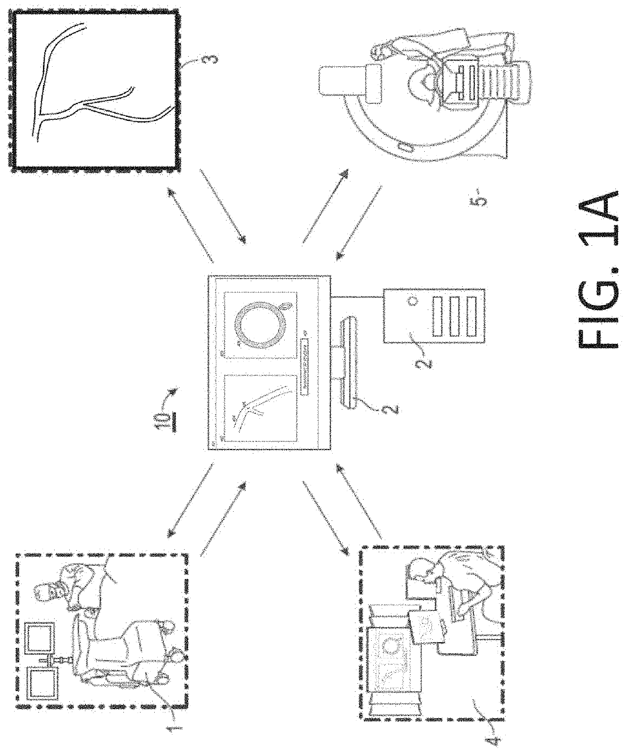
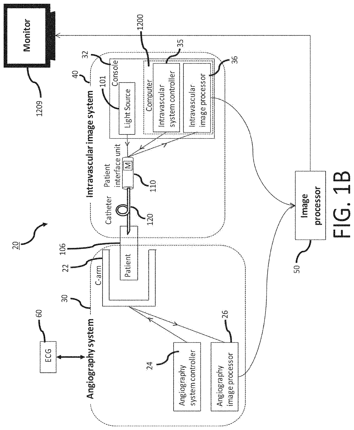
[0038]One or more devices, systems, methods and storage mediums for characterizing tissue, or an object, using one or more imaging techniques or modalities (such as, but not limited to, OCT, fluorescence, NIRAF, etc.) are disclosed herein. Several embodiments of the present disclosure, which may be carried out by the one or more embodiments of an apparatus, system, method and / or computer-readable storage medium of the present disclosure are described diagrammatically and visually in FIGS. 1A through 12.

[0039]Turning now to the details of the figures, imaging modalities may be displayed in one or more ways as discussed herein. One or more displays discussed herein may allow a user of the one or more displays to use, control and / or emphasize multiple imaging techniques or modalities, such as, but not limited to, OCT, NIRAF, etc., and may allow the user to use, control, and / or emphasize the multiple imaging techniques or modalities synchronously.

[0040]As shown diagrammatically in FIG. ...


PUM


Abstract

One or more devices, systems, methods and storage mediums for optical imaging medical devices, such as, but not limited to, Optical Coherence Tomography (OCT), single mode OCT, and / or multi-modal OCT apparatuses and systems, and methods and storage mediums for use with same, for viewing, controlling, updating, and emphasizing one or more imaging modalities and / or for constructing or reconstructing 2D and / or 3D structure(s) are provided herein. One or more embodiments provide at least one intuitive Graphical User Interface (GUI), method, device, apparatus, system, or storage medium to comprehend information, including, but not limited to, molecular structure of a vessel, and to provide an ability to manipulate the vessel information and / or to construct or reconstruct 2D and / or 3D structure(s) of the vessel to improve or maximize accuracy in one or more images. In addition to controlling one or more imaging modalities, the GUI may operate for one or more applications, including, but not limited to, expansion / underexpansion (e.g., for a stent) and / or apposition / malapposition (e.g., for a stent), co-registration, and imaging.

Description

CROSS-REFERENCE TO RELATED APPLICATION(S)[0001]This application relates, and claims priority, to U.S. Patent Application Ser. No. 62 / 901,472, filed Sep. 17, 2019, the entire disclosure of which is incorporated by reference herein in its entirety.FIELD OF THE INVENTION[0002]This present disclosure generally relates to computer imaging and / or to the field of optical imaging, particularly to devices / apparatuses, systems, methods, and storage mediums for constructing or reconstructing three-dimensional (3D) structure(s) and / or for using one or more imaging modalities, such as, but not limited to, angiography, Optical Coherence Tomography (OCT), Multi-modality OCT (MM-OCT), near-infrared fluorescence (NIRAF), OCT-NIRAF, etc. Examples of OCT applications include imaging, evaluating and diagnosing biological objects, such as, but not limited to, for gastro-intestinal, cardio and / or ophthalmic applications, and being obtained via one or more optical instruments, such as, but not limited to,...

Claims


Application Information

Patent Timeline
Patent Type & Authority Applications(United States)
IPC IPC(8): A61B6/12A61B5/02A61B5/00A61B5/107A61B8/08A61B8/12A61B6/00G06T7/00G06T7/30G06T7/70
CPCA61B6/12G06T2207/30104A61B5/0066A61B5/1076A61B8/0891A61B8/12A61B6/504A61B6/5217A61B6/5247A61B6/463A61B6/466A61B6/465A61B6/469A61B6/507G06T7/0014G06T7/30G06T7/70G06T2207/10064G06T2207/10101G06T2207/10048G06T2207/10028G06T2207/10088G06T2207/10081G06T2207/10116G06T2207/10132G06T2207/30096A61B5/02007G06T7/33G06T2207/10121G06T2207/10068G06T2207/30048G06T2207/30101
Inventor KUNIO, MIE
Owner CANON USA
Why Eureka
Try Eureka