Turbine stator blade cooled by air-jet impacts

a stator blade and turbine technology, applied in the direction of stators, machines/engines, mechanical equipment, etc., can solve the problems of limiting the service life of the insert, affecting the efficiency of the turbine, so as to achieve the effect of reducing the size of the inser

Active Publication Date: 2021-03-25
SAFRAN HELICOPTER ENGINES
View PDF0 Cites 0 Cited by
  • Summary
  • Abstract
  • Description
  • Claims
  • Application Information

AI Technical Summary

Benefits of technology

[0010]The present invention therefore aims at overcoming the aforementioned drawbacks by proposing an impingement cooled turbomachine blade which is: thermally effective, that is to say which allows dissipating a high thermal power by using a moderate air flow rate; sealed, that is to say which allows ensuring that the air mobilized is only dedicated to the cooling of the blade (the higher the sealing of the device the greater its overall effectiveness); compact, that is to say the integration of the cooling device must minimize its impingement on the overall dimension of the engine; cost-effective, that is to say the production cost of the cooling device must be the lowest possible and finally which can be manufactured by additive manufacturing. It also relates to any turbomachine turbine fitted with such cooled blades per through insert.

Problems solved by technology

These turbine blades are subjected to the very high temperatures of the combustion gases which reach values significantly greater than those that the blades in direct contact with these gases can withstand without damage, which has the consequence of limiting their service life.
However, the integration of the insert into the hollow airfoil is expensive, leaky and the control of the distance between the insert and the inner surface of the airfoil is relatively delicate.
However, the disadvantages of such an cooling with integrated insert by additive manufacturing are numerous and in particular related to the manufacturability on a unitary diffuser whose manufacturing direction is imposed and can only be that of the drive axis.
Indeed, any other choice in the manufacturing direction would lead to having a manufacturing direction per blade, which is impossible to implement without significantly increasing the production costs.
In addition, this direction (according to the drive axis) implies that the insert is manufactured in the “vacuum” and thus that some surfaces called “downskin” are therefore likely to collapse.
However, for the sealing of the cooling circuit to be perfect, it would therefore be necessary to embed it at both ends by integrating it directly into the blade, which, given the fact that the average temperature of the insert is much lower than that of the airfoil (on the order of a hundred degrees), is not possible because the insert would then be mechanically too stressed.
However, to this day, it is impossible to achieve such a narrow adjustment because the additive manufacturing currently allows only minimum clearances greater than 0.2 mm (which is 20 times greater than the desired adjustment).

Method used


Image

  • Turbine stator blade cooled by air-jet impacts
  • Turbine stator blade cooled by air-jet impacts
  • Turbine stator blade cooled by air-jet impacts

Examples


Embodiment Construction

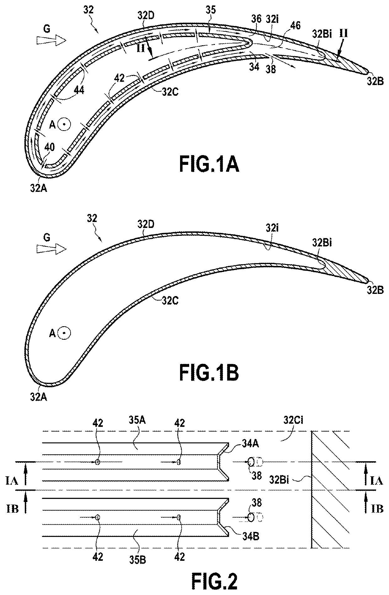
[0026]FIGS. 1A and 1B represent in axial section a cooled blade assembly, for example a turbine diffuser of a turbomachine according to the present invention. This blade formed of a hollow airfoil 32 is fixed to a casing (not represented) of the turbine in the flow path of the combustion gases through the turbine whose direction of flow of these gases is illustrated by the arrow referenced G in the figure. A leading edge 32A and a trailing edge 32B opposite to each other and intrados 32C and extrados 32D walls extending radially between a blade root and a blade tip are defined for this airfoil 32.

[0027]Such a blade is subjected to the very high temperatures of the combustion gases and therefore needs to be cooled. For this purpose, a cooling circuit supplied with cooling air at one of its radial ends (the cooling air stream which, in the figure, moves along a radial axis of the blade, from the blade tip to the blade root, is represented by the arrow referenced A), is formed by a plu...


PUM


Abstract

A turbomachine blade formed of a hollow airfoil having a leading edge and a trailing edge opposed to each other and connected by an intrados wall and an extrados wall each extending along a radial axis of the blade, between a blade root and a blade tip, and including a cooling circuit supplied with air and delivering air jets ensuring through multiple perforations of the cooling circuit an impingement cooling of the inner surface of the airfoil, the cooling circuit includes superimposed cooling channels over the height of the blade, each integrated into the inner surface of the airfoil while matching its contour, the multiple perforations being drilled in the cooling channels terminating in a purge cavity of the airfoil are able to ensure a purge of the air having impinged the inner surface of the airfoil after its passage through the perforations.

Description

BACKGROUND OF THE INVENTION[0001]The present invention relates to the general field of blade assemblies for a turbomachine turbine, and more particularly to the turbine blades fitted with integrated cooling circuits.[0002]In a manner known per se, a turbomachine includes a combustion chamber in which air and fuel are mixed before being burned therein. The gases resulting from this combustion flow downstream of the combustion chamber and then supply a high-pressure turbine and a low-pressure turbine. Each turbine includes one or several rows of fixed blades (called diffuser) alternating with one or several rows of movable blades (called impellers), spaced circumferentially all around the rotor of the turbine. These turbine blades are subjected to the very high temperatures of the combustion gases which reach values significantly greater than those that the blades in direct contact with these gases can withstand without damage, which has the consequence of limiting their service life....

Claims


Application Information

Patent Timeline
Patent Type & Authority Applications(United States)
IPC IPC(8): F01D5/18
CPCF01D5/189F05D2250/13F05D2260/201F05D2220/30F05D2250/11F01D9/065F05D2250/23F05D2250/313Y02T50/60
Inventor HALLOUIN, BAPTISTECASAUX-BIC, JEAN-MAURICEMONTPELLAZ, ALEXANDRERENAULT, LIONEL
Owner SAFRAN HELICOPTER ENGINES
Why Eureka
Try Eureka