Medical Imaging Device and Image Processing Method

a medical imaging and image processing technology, applied in the field of medical imaging devices, can solve the problems of requiring surface traces, time-consuming, and the step of selecting the measurement image after acquiring images takes the most time and effort, and achieves the effects of reducing manual operation dependence, high degree of precision, and reducing examination tim

Inactive Publication Date: 2021-03-25
FUJIFILM HEALTHCARE CORP
View PDF3 Cites 0 Cited by
  • Summary
  • Abstract
  • Description
  • Claims
  • Application Information

AI Technical Summary

Benefits of technology

[0012]According to the present invention, the learning model is applied to extraction of the cross section, thereby achieving reduction of manual-operation dependence and also reduction of examination time, in automatic extraction of the cross sectional image optimum for measurement. In addition, the small and simple model, being downsized with keeping a high degree of precision, is employed as the precise and complex learning model. Accordingly, this allows installation of the learning model on the medical imaging device, with maintaining a standard scale of an image processor within the device, as well as achieving high-speed processing.

Problems solved by technology

Measuring the head region or the abdominal region requires surface traces, and it has been time consuming.
In the examination, however, the step of selecting of the measurement image after acquiring images takes the most time and effort.
For the case of a fetus, in particular, it is difficult to estimate and visualize a position of a measurement cross section, within the abdomen of the fetus as the examinee, and thus it takes time to acquire the cross section.

Method used


Image

  • Medical Imaging Device and Image Processing Method
  • Medical Imaging Device and Image Processing Method
  • Medical Imaging Device and Image Processing Method

Examples


first embodiment

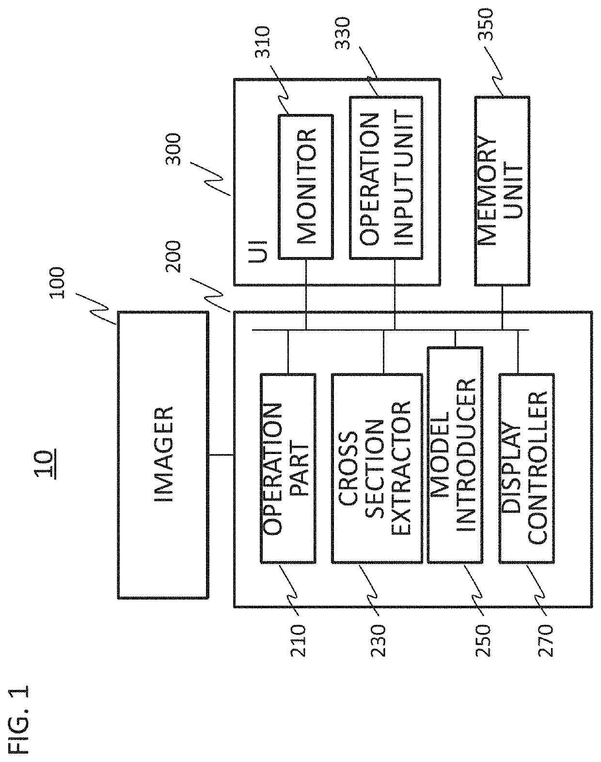
[0029]As shown FIG. 1, a medical imaging device 10 of the present embodiment is provided with an imager 100 configured to take an image of a subject and acquire image data, an image processor 200 configured to perform image processing on the image data acquired by the imager 100, a monitor 310 configured to display an image acquired by the imager 100 or an image processed by the image processor 200, and an operation input unit 330 for a user to enter commands and data necessary for the processing in the imager 100 and in the image processor 200. Typically, the monitor 310 is placed in proximity to the operation input unit 330, functioning as a user interface (UI) 300. The medical imaging device 10 may further be provided with a memory unit 350 for storing the image data obtained by the imager 100, data used in the processing by the image processor 200, and processing results thereof.

[0030]The imager 100 may be structured variously depending on modality. For the case of an MRI device...

second embodiment

Modification of Second Embodiment

[0087]In the aforementioned embodiments, there has been described the case where the volume data imaged in one-time examination for one patient is processed. The present embodiment is applicable to a group of 2D images taken in the examination at a previous time or in the examinations across the past several times. There will now be described the case where input data is 2D images that are temporally sequential.

[0088]FIG. 15 illustrates data acquisition and generation of a group of cross sections from data memory, when an extraction target is sequential 2D cross sections on temporal axis. In the present embodiment, a 1D probe is moved on the fetus 101 being an examination target, and temporally sequential 2D cross sections are accumulated in the data memory 472. Sampling of the cross section data 1501 called from the data memory 472 is performed on the temporal axis, and a target group of cross sections 1502 are generated. In other words, the search ...


PUM


Abstract

Provided is a technique for automatically extracting a cross section with a high degree of precision and at high speed, with avoiding problems of operator dependence and imaging target dependence, from 3D volume data or temporally sequential 2D or 3D images or 3D volume data, acquired by a medical imaging device, when determining the cross section used for diagnosis and measurement. An image processor of an imaging device is provided with a cross section extractor for extracting a specified cross section from imaged data. The cross section extractor determines the specified cross section by using a learning model trained in advance to output discrimination scores for a plurality of cross sectional image data, the discrimination score representing spatial or temporal proximity to the specified cross section. The learning model is a downsized model obtained by integrating a highly trained model having a large number of layers, with an untrained model having less number of layers, followed by retraining.

Description

TECHNICAL FIELD[0001]The present invention relates to a medical imaging device, including an ultrasound imaging device, an MRI device, and a CT device. More particularly, the present invention relates to techniques for selecting a specified cross section to be displayed, from a three-dimensional image, or two-dimensional (2D) time-series images or three-dimensional (3D) time-series images, being acquired by the medical imaging device.BACKGROUND ART[0002]Medical imaging devices are used to acquire and then display a morphological image of a target region. In addition, the medical imaging devices can also be used to acquire morphological information and functional information quantitatively. One of examples of such usage may be measurement of estimated weight of an unborn baby (fetus) for observing growth thereof, by the use of an ultrasound imaging device. This type of measurement is performed according to a process, roughly divided into three steps; acquiring images, selecting an im...

Claims


Application Information

Patent Timeline
Patent Type & Authority Applications(United States)
IPC IPC(8): G06K9/62G06K9/46G06K9/20A61B8/14A61B8/00A61B8/08G06V10/764
CPCG06K9/623G06K9/46G06K9/2081G06K2209/05A61B8/4444A61B8/5207A61B8/14G06T1/00A61B6/032A61B6/5223A61B8/483A61B8/0866A61B8/523A61B8/5223A61B8/465G06N3/08G06V2201/03G06V10/82G06V10/764G06N3/045G06F18/2113
Inventor LI, YUNTOYOMURA, TAKASHIMAEDA, TOSHINORILI, ZISHENG
Owner FUJIFILM HEALTHCARE CORP
Why Eureka
Try Eureka