Millimeter wave conformal slot antenna

a technology of conformal antennas and millimeter wave, which is applied in the direction of slot antennas, antennas, electrical equipment, etc., can solve the problem of negative impact on the performance of antennas

Active Publication Date: 2021-03-25
BAE SYST INFORMATION & ELECTRONICS SYST INTERGRATION INC
View PDF0 Cites 1 Cited by
  • Summary
  • Abstract
  • Description
  • Claims
  • Application Information

AI Technical Summary

Problems solved by technology

Typically, antennas operating at millimeter wave (mmW) frequencies need to have components with tight tolerances of the parts and their placement relative to a wavelength in the 20-40 GHz range and this negatively impacts performance of the antenna if these requirements are not met.

Method used


Image

  • Millimeter wave conformal slot antenna
  • Millimeter wave conformal slot antenna
  • Millimeter wave conformal slot antenna

Examples


Embodiment Construction

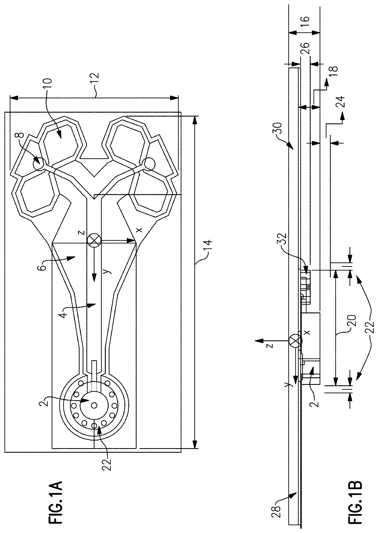
[0022]There was a need for a conformal antenna with near positive gain and hemispherical gain coverage. Power consumption can be an issue for some systems, therefore if higher gain numbers can be achieved less power is required in the transmit assembly for those systems. In a transmitting antenna, the gain describes how well the antenna converts input power into radio waves headed in a specified direction. In a receiving antenna, the gain describes how well the antenna converts radio waves arriving from a specified direction into electrical power. When no direction is specified, “gain” is understood to refer to the peak value of the gain, the gain in the direction of the antenna's main lobe. A plot of the gain as a function of direction is called the gain pattern or radiation pattern. Having hemispherical gain coverage helps reduce the number of antennas and transmit assemblies required if coverage a wide field of view is required. In one embodiment of the present disclosure, a slot...


PUM


Abstract

The system and method for a conformal millimeter wave (mmW) cavity backed slot antenna with near positive gain and hemispherical gain coverage. The antenna has a microstrip launch and feed and a surface mount connector. The mmW antenna may have a stripline launch or waveguide launch instead of a microstrip launch. In some cases, the microwave electronics can be mounted on the launch substrate instead of a connector.

Description

FIELD OF THE DISCLOSURE[0001]The present disclosure relates to conformal antennas in the millimeter wave (mmW) frequency range and more particularly to a conformal antenna in the mmW frequency range with near positive gain and hemispherical gain coverage.BACKGROUND OF THE DISCLOSURE[0002]Typically, antennas operating at millimeter wave (mmW) frequencies need to have components with tight tolerances of the parts and their placement relative to a wavelength in the 20-40 GHz range and this negatively impacts performance of the antenna if these requirements are not met. A slot antenna consists of a metal surface, usually a flat plate, with one or more holes or slots cut out. When the plate is driven as an antenna by a driving frequency, the slot radiates electromagnetic waves in a way similar to a dipole antenna. The shape and size of the slot, as well as the driving frequency, determine the radiation pattern. Often the radio waves are provided by a waveguide, and the antenna consists o...

Claims


Application Information

Patent Timeline
Patent Type & Authority Applications(United States)
IPC IPC(8): H01Q1/38H01Q13/10
CPCH01Q1/38H01Q13/106H01Q13/18
Inventor HOWARTH, DEAN W.JENSEN, JONOTHAN S.
Owner BAE SYST INFORMATION & ELECTRONICS SYST INTERGRATION INC
Why Eureka
Try Eureka