
Particle detectors with remote alarm monitoring and control

a technology of alarm monitoring and control, which is applied in the field of particle detectors, can solve the problems of pharmaceutical products at risk of failing to meet the cleanliness level standards, real-time efficiency, and fabrication efficiency drop

Active Publication Date: 2021-04-08
PARTICLE MEASURING SYST
View PDF0 Cites 2 Cited by
  • Summary
  • Abstract
  • Description
  • Claims
  • Application Information

AI Technical Summary

Benefits of technology

The patent text is about devices and methods that are disclosed without being limited to a specific theory. The text recognizes that regardless of the accuracy of any explanation or hypothesis, the invention can still be used and useful. The technical effect of the patent is the ability to create devices and methods that can be used even without a complete understanding of the underlying principles.

Problems solved by technology

For the semiconductor industry, an increase in airborne particulate concentration can result in a decrease in fabrication efficiency, as particles that settle on semiconductor wafers will impact or interfere with the small length scale manufacturing processes.
For the pharmaceutical industry, where this type of real-time efficiency feedback is lacking, contamination by airborne particulates and biological contaminants puts pharmaceutical products at risk for failing to meet cleanliness level standards established by the US Food and Drug Administration (FDA) and other foreign and international health regulatory agencies.
Thus, audible alarms that emanate from the particle detection device itself may not be heard, or it may be difficult to ascertain which device has entered an alarm state.
Additionally, audible and / or visual alarms may not be visible from locations remote of the particle detection devices

Method used


Image

  • Particle detectors with remote alarm monitoring and control
  • Particle detectors with remote alarm monitoring and control
  • Particle detectors with remote alarm monitoring and control

Examples


Embodiment Construction

[0038]In general, the terms and phrases used herein have their art-recognized meaning, which can be found by reference to standard texts, journal references and contexts known to those skilled in the art. The following definitions are provided to clarify their specific use in the context of the invention.

[0039]“Particle” refers to a small object which is often regarded as a contaminant. A particle can be any material created by the act of friction, for example when two surfaces come into mechanical contact and there is mechanical movement. Particles can be composed of aggregates of material, such as dust, dirt, smoke, ash, water, soot, metal, minerals, or any combination of these or other materials or contaminants. “Particles” may also refer to biological particles, for example, viruses, spores and microorganisms including bacteria, fungi, archaea, protists, other single cell microorganisms. Biological particles include, but are not limited to, microorganisms having a size on the or...


PUM


Abstract

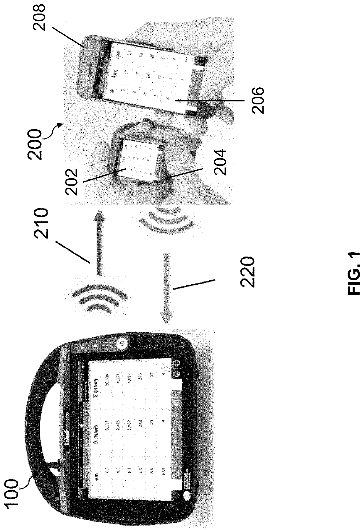
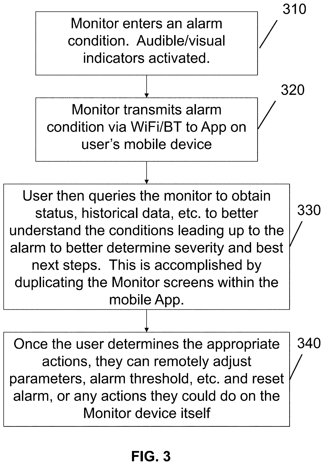
The invention generally provides devices and methods for particle detection for minimizing human-caused contamination in manufacturing environments requiring low levels of microbes, such as cleanroom environments for electronics manufacturing and aseptic environments for manufacturing pharmaceutical and biological products, such as sterile medicinal products. Methods of the invention may incorporate wirelessly transmitting an alarm signal from a particle detector to a remote device, replicating a graphical user interface of the particle detector on an electronic display of the remote device, and passing one or more user instructions from the remote device to the particle detector via the replicate graphical interface of the remote device.

Description

CROSS-REFERENCE TO RELATED APPLICATIONS[0001]This application claims the benefit of priority to U.S. Provisional Patent Application No. 62 / 911,810, filed Oct. 7, 2019, which is hereby incorporated by reference in its entirety.STATEMENT REGARDING FEDERALLY SPONSORED RESEARCH OR DEVELOPMENT[0002]Not applicable.BACKGROUND OF INVENTION[0003]This invention is in the field of particle sampling, collection and analysis. This invention relates generally to particle detectors having remote alarm monitoring and control capabilities.[0004]Cleanrooms and clean zones are commonly used in semiconductor and pharmaceutical manufacturing facilities. For the semiconductor industry, an increase in airborne particulate concentration can result in a decrease in fabrication efficiency, as particles that settle on semiconductor wafers will impact or interfere with the small length scale manufacturing processes. For the pharmaceutical industry, where this type of real-time efficiency feedback is lacking, c...

Claims


Application Information

Patent Timeline
Patent Type & Authority Applications(United States)
IPC IPC(8): G08B21/14G08B21/18G08B27/00
CPCG08B21/14G08B27/008G08B21/182G01N1/2273G01N35/00871G01N2035/0091G01N2035/009G01N2015/0046G01N15/1459G06F3/04847H04M1/72412G01N15/1429G01N15/0211G01N1/22G06F3/04817G06F3/0484G01N2015/1486
Inventor MACLAUGHLIN, SCOTTMICHAELIS, MATT
Owner PARTICLE MEASURING SYST
Learn More