Honeycomb structure

Pending Publication Date: 2021-04-15
NGK INSULATORS LTD
View PDF54 Cites 0 Cited by
  • Summary
  • Abstract
  • Description
  • Claims
  • Application Information

AI Technical Summary

Benefits of technology

[0025]The honeycomb structure of the present invention has the remarkable effect of effectively suppressing a decrease in isostatic strength and an increase in pressure loss while increasing the allowable amount of the catalyst that can be loaded on the partition wall and effectively utilizing the catalyst loaded in th

Problems solved by technology

A honeycomb structure having the partition wall with higher porosity, however, has a problem of a decrease in isostatic strength.
A honeycomb structure with higher cell density has a problem of an increase in pressure loss of the honeycomb structure.
The partition wall having a reduced thickness as well as with higher porosity as described above makes it more difficult to keep the isostatic strength and the like.
This ho

Method used


Image

  • Honeycomb structure
  • Honeycomb structure

Examples


example 1

[0058]2.5 parts by mass of pore former, 0.5 part by mass of dispersing medium, and 6.5 parts by mass of organic binder were added to 100 parts by mass of the cordierite forming raw material, followed by mixing and kneading to prepare a kneaded material. As the cordierite forming raw material, alumina, aluminum hydroxide, kaolin, talc, and silica were used. As the dispersing medium, water was used. As the organic binder, methylcellulose was used. As the dispersing agent, dextrin was used. As the pore former, hollow resin particulates having the average particle diameter of 28 μm were used.

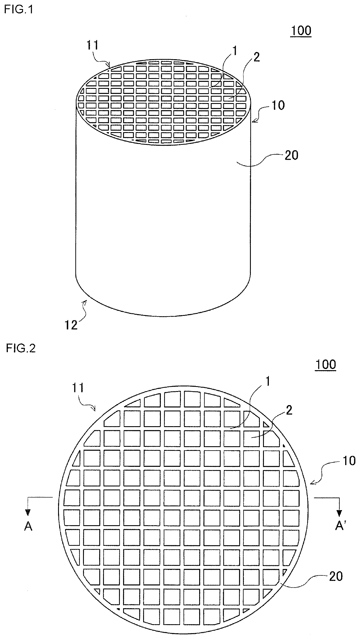
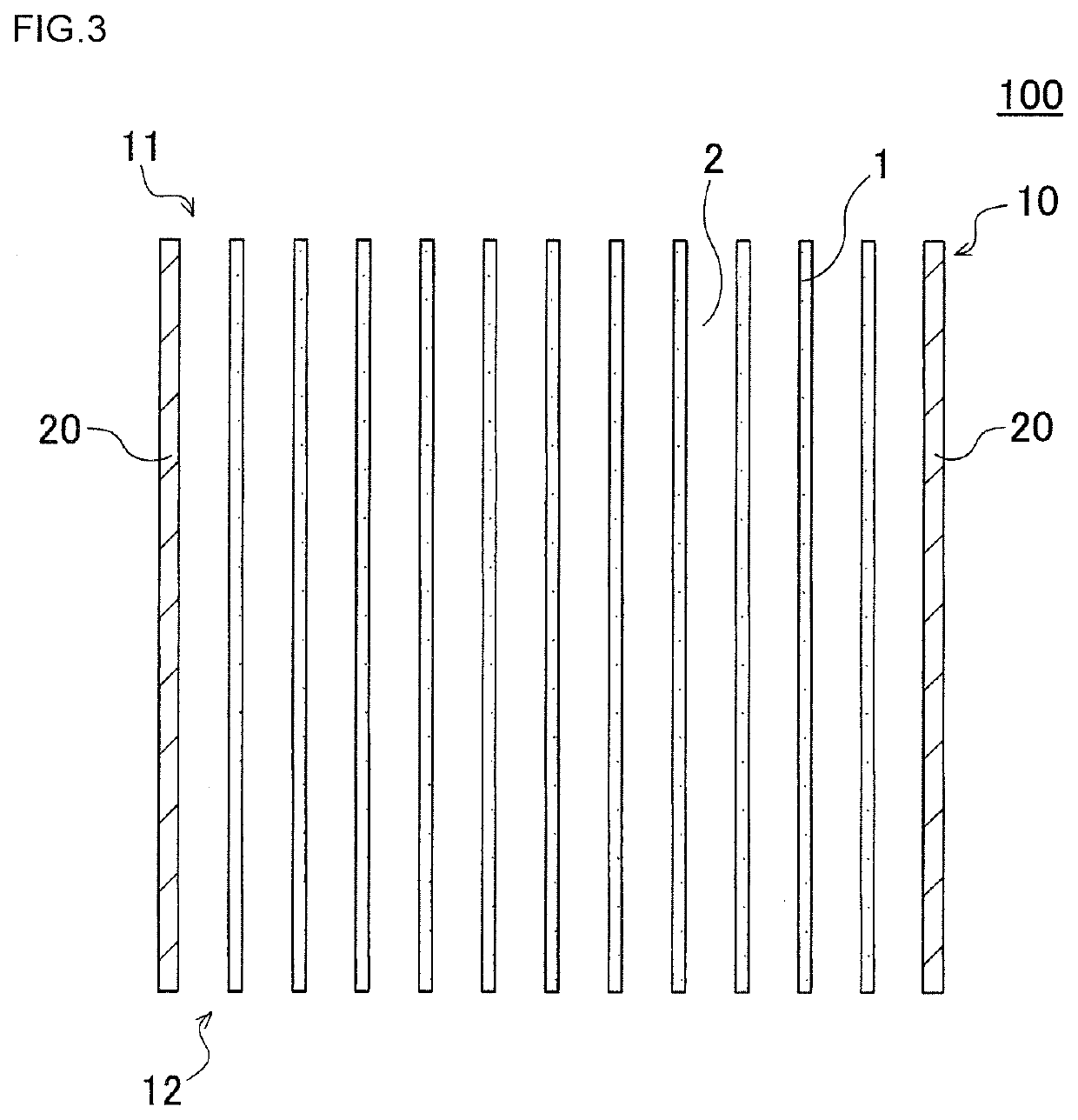
[0059]Next, the kneaded material was extruded using a die for manufacturing of a honeycomb formed body to have a honeycomb formed body having a round pillar shape as the overall shape. The cells of the honeycomb formed body had a quadrangular shape.

[0060]Next, the honeycomb formed body was dried by a microwave dryer, then was dried completely by a hot-air drier, and then both end faces of the honeyc...

examples 2 to 21

[0076]Honeycomb structures of Examples 2 to 21 were manufactured by changing the structure of the partition wall as in Table 1. The “Average pore diameter (μm)”, the “Pore volume ratio of first pores (%)”, the “Pore volume ratio of second pores (%)” and the “Value of the pore diameter between peaks in the pore diameter distribution (μm)” were adjusted by adjusting the particle diameter of the pore former added to the forming raw material.

[0077]In Example 2, the pore former having the average particle diameter of 28 μm was used.

[0078]In Example 3, the pore former having the average particle diameter of 38 μm was used.

[0079]In Example 4, the pore former having the average particle diameter of 28 μm was used.

[0080]In Example 5, the pore former having the average particle diameter of 70 μm was used.

[0081]In Example 6, the pore former having the average particle diameter of 70 μm was used.

[0082]In Example 7, the pore former having the average particle diameter of 10 μm was used.

[0083]In ...


PUM

PropertyMeasurementUnit
Lengthaaaaaaaaaa
Lengthaaaaaaaaaa
Lengthaaaaaaaaaa

Abstract

A honeycomb structure includes a pillar-shaped honeycomb structure body having a porous partition wall disposed to surround a plurality of cells, wherein a major component of the partition wall is cordierite, a porosity of the partition wall is 45 to 55%, an average pore diameter of the partition wall is 8 to 19 μm, a cumulative pore volume of the partition wall is such that a pore volume ratio of the pores having a pore diameter larger than a thickness of the partition wall relative to an overall pore volume of the partition wall is 3.0% or less, and a pore volume ratio of the pores having a pore diameter of 10 μm or less relative to the overall pore volume of the partition wall is 30% or more, and a pore diameter distribution of the partition wall is a unimodal distribution, or a multimodal distribution.

Description

[0001]The present application is an application based on JP 2019-187529 filed on Oct. 11, 2019 with Japan Patent Office, the entire contents of which are incorporated herein by reference.BACKGROUND OF THE INVENTIONField of the Invention[0002]The present invention relates to honeycomb structures. More specifically the present invention relates to a honeycomb structure that can be particularly suitably used for a catalyst carrier to be loaded with catalyst to purify exhaust gas.Description of the Related Art[0003]Currently, developed countries are examining to tighten the standards on NOx emission from diesel vehicles and tracks more. To meet such NOx emission standards, various techniques have been proposed to treat NOx in exhaust gas. One of these techniques manufactures a honeycomb structure having a porous partition wall loaded with selective catalytic reduction catalyst (hereinafter this may be called “SCR catalyst”), for example, to treat NOx in exhaust gas with the honeycomb st...

Claims


Application Information

Patent Timeline
IPC IPC(8): B01J35/04B01J21/04B01J35/10B01D53/94
CPCB01J35/04B01J21/04B01D2255/50B01D53/94B01D2255/9155B01J35/1052B01J35/1076B01J35/10C04B38/0009B01D53/9409C04B2111/00793C04B2111/0081C04B35/195C04B38/0064C04B38/0074
Inventor KURIMOTO, YUDAIHIROSE, SHOGO
Owner NGK INSULATORS LTD
Why Eureka
Try Eureka