Honeycomb structure

a honeycomb and structure technology, applied in the field of honeycomb structure, can solve the problems of shifting difficulty in acquiring the isostatic strength of the honeycomb structure, and damage to the honeycomb structure, and achieve excellent thermal shock resistance, effective inhibiting the shift of the honeycomb structure, and excellent thermal shock resistance

Active Publication Date: 2017-11-16
NGK INSULATORS LTD +1
View PDF1 Cites 7 Cited by
  • Summary
  • Abstract
  • Description
  • Claims
  • Application Information

AI Technical Summary

Benefits of technology

[0019]According to a honeycomb structure of the present invention, it is possible to effectively inhibit shift of the honeycomb structure in a can member when receiving the honeycomb structure in the can member to use the honeycomb structure as a filter, a catalyst carrier or the like. Furthermore, in the honeycomb structure of the present invention, a honeycomb structure body and a supporting bulge are monolithically formed, circumferential coating materials are not used in an outer wall, and hence the honeycomb structure is excellent in thermal shock resistance. Furthermore, the honeycomb structure of the present invention is excellent in thermal shock resistance as described above, and hence it is possible to achieve a high porosity of partition walls. In circumstances where a catalyst is loaded into the partition walls, pressure loss is low, and a heat capacity of the honeycomb structure is small, whereby it is possible to shorten time required for catalyst activation.
[0020]More specifically, the honeycomb structure of the present invention includes a porous supporting bulge disposed to extend out from a circumference of the outer wall so that a part of the outer wall is exposed. Furthermore, the supporting bulge has a plurality of support portions protruding from the circumference of the outer wall toward the outside of the outer wall, and at least one side wall portion supported by the support portions. Further in the honeycomb structure of the present invention, the partition walls and the outer wall of the honeycomb structure body and the support portions and the side wall portion of the supporting bulge are all formed monolithically by formation of a ceramic raw material. That is, in the honeycomb structure of the present invention, the outer wall of the honeycomb structure body is not made of the circumferential coating material, but is formed monolithically with the other constituent elements (e.g., the partition walls, the support portions and the side wall portion). Therefore, the thermal shock resistance of the honeycomb structure is remarkably high. Here, the honeycomb structure of the present invention includes the porous supporting bulge disposed to extend out from the circumference of the outer wall, whereby when the honeycomb structure is received in the can member, movement of the honeycomb structure body in a cell extending direction can be inhibited by the supporting bulge. Consequently, according to the honeycomb structure of the present invention, it is not necessary to apply a high holding pressure to the honeycomb structure. Therefore, even when a thickness of the partition walls of the honeycomb structure is decreased or a porosity of a substrate is increased to decrease an isostatic strength of the honeycomb structure, it is possible to inhibit the honeycomb structure from being damaged by the holding pressure.

Problems solved by technology

However, when the thickness of the partition walls of the honeycomb structure is decreased or the porosity of the substrate is increased, it becomes difficult to acquire an isostatic strength of the honeycomb structure.
When the isostatic strength of the honeycomb structure is low, the honeycomb structure might be damaged by a holding pressure applied to a circumference of the honeycomb structure at the time of receiving the honeycomb structure in the can member.
When the holding pressure is decreased to avoid the damages on the honeycomb structure, there is the problem that the honeycomb structure shifts from a predetermined received position in circumstances where an exhaust gas pressure or vibration is applied to the honeycomb structure.

Method used


Image

  • Honeycomb structure
  • Honeycomb structure
  • Honeycomb structure

Examples


example 1

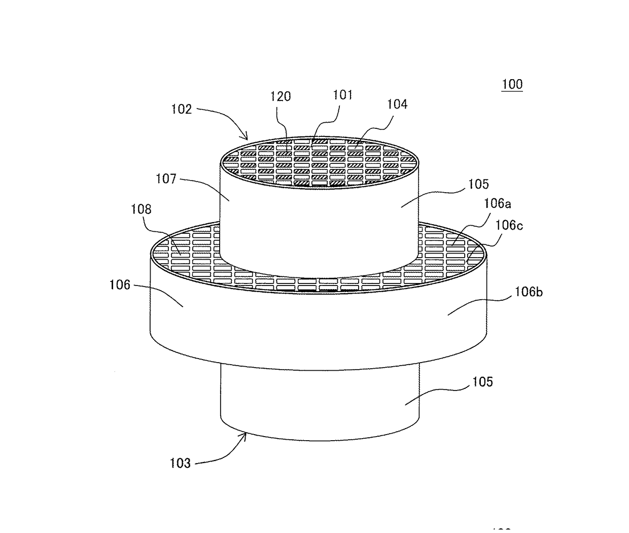
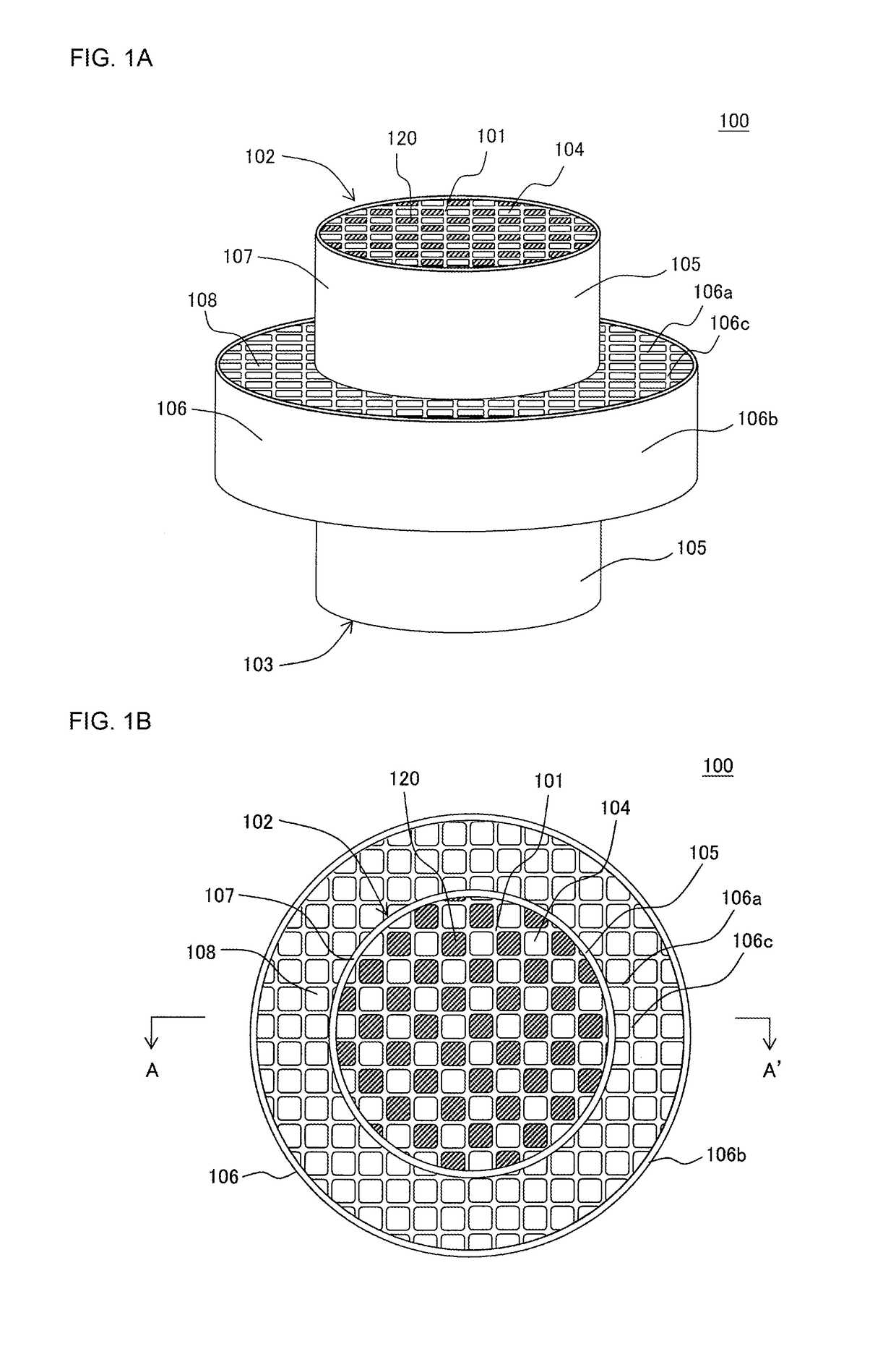
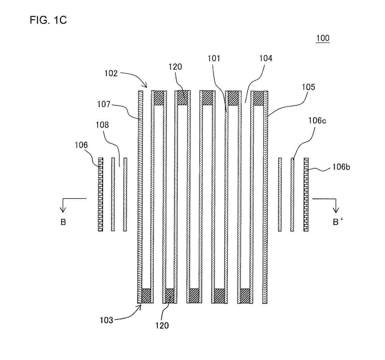
[0085](Honeycomb Structure)

[0086]To 100 parts by mass of a cordierite forming raw material, there were added 13 parts by mass of a pore former, 35 parts by mass of a dispersing medium, 6 parts by mass of an organic binder and 0.5 part by mass of a dispersing agent, respectively, followed by mixing and kneading, to prepare a kneaded material. As the cordierite forming raw material, alumina, aluminum hydroxide, kaolin, talc and silica were used. Water was used as the dispersing medium, cokes having an average particle diameter of 1 to 10 μm were used as the pore former, hydroxypropyl methylcellulose was used as the organic binder, and ethylene glycol was used as the dispersing agent. Particle diameters and an amount of the pore former were controlled to control pore diameters and a porosity of partition walls.

[0087]Next, the kneaded material was extruded by using a predetermined die, to obtain a honeycomb formed body in which a honeycomb precursor having a quadrangular cell shape and ...

examples 2 to 9

[0105]In Examples 2 to 7, the procedure of Example 1 was repeated except that a thickness (mm) of partition walls, a porosity (%) and an average pore diameter (μm) were changed as shown in Table 1, to prepare honeycomb structures. On the other hand, in Examples 8 and 9, the procedure of Example 1 was repeated except that a length of each honeycomb structure and a length of each supporting bulge were changed, to prepare honeycomb structures. In Example 8, the length of the honeycomb structure was set to 152 mm and the length of the supporting bulge was set to 2 mm. In the honeycomb structure of Example 8, a value of “S2 / (S1+S2)” was 0.01. In Example 9, the length of the honeycomb structure was set to 91 mm and a length of a supporting bulge was set to 75 mm. In the honeycomb structure of Example 9, a value of “S2 / (S1+S2)” was 0.8.


PUM

PropertyMeasurementUnit
porositiesaaaaaaaaaa
pore diametersaaaaaaaaaa
thicknessaaaaaaaaaa

Abstract

A honeycomb structure includes a pillar-shaped honeycomb structure body including porous partition walls defining and forming a plurality of cells which extend from an inflow end face to an outflow end face, and a porous outer wall surrounding the partition walls, a porous supporting bulge disposed to extend out from a circumference of the outer wall so that at least a part of the outer wall is exposed, and plugging portions arranged in open ends of the cells, and the supporting bulge has support portions and a side wall portion, and the partition walls and the outer wall of the honeycomb structure body and the support portions and the side wall portion of the supporting bulge are all formed monolithically by formation of a ceramic raw material.

Description

TECHNICAL FIELD[0001]The present invention relates to a honeycomb structure, and more particularly, it relates to a honeycomb structure which is easily manufactured to be excellent in thermal shock resistance, and is prevented from being shifted in a can member when the honeycomb structure is received in the can member which receives the honeycomb structure.BACKGROUND ART[0002]Honeycomb structures have broadly been used in filters, catalyst carriers and the like, and have especially broadly been used as exhaust gas purifying and exhaust gas treating catalyst carriers, filters and the like in internal combustion engines such as a gasoline engine and a diesel engine, and burning devices.[0003]Especially, the honeycomb structure for use as the exhaust gas purifying catalyst carrier or filter or the like in a gasoline engine car, a diesel engine car or the like is required to have an improved purification performance to cope with exhaust gas regulations which are yearly strengthened in ...

Claims


Application Information

Patent Timeline
Patent Type & Authority Applications(United States)
IPC IPC(8): B01J35/04B01D39/20F01N3/022B01D46/24B01D53/94B01J23/745C04B38/06C04B38/00C04B35/195B01J37/08B01J37/00F01N3/28
CPCB01J35/04B01D39/20B01D46/247B01D46/2474B01D53/94C04B35/195B01J37/0009B01J37/08B01J37/0018C04B38/0695C04B38/0012B01J23/745F01N3/0222F01N3/2842B01D2046/2437B01D2046/2481B01D2279/30C04B2235/606C04B2235/6021C04B38/00C04B38/06F01N3/28F01N2330/10F01N2330/30F01N2330/60B01J35/10C04B2235/3217C04B2235/3218C04B2235/3418C04B2235/3445C04B2235/349C04B2235/5292C04B38/0006C04B2111/00793C04B2111/0081C04B2111/2084B01D46/249B01D46/24492B01D46/24491B01D46/2484B01D46/2476B01D46/2482B01D46/2492C04B38/0051F01N3/022F01N3/2803B01D46/2496B01D46/2425B01D46/2429B01D46/2488B01D46/2494B01D46/2486
Inventor AOKI, TAKASHIWAKIDA, NORIHIROHATAKEYAMA, YOSHIAKI
Owner NGK INSULATORS LTD
Why Eureka
Try Eureka