Router Bit Holding Vise

a router bit and vise technology, applied in the field of router bits, can solve the problems of difficult function, large torque, and other problems, and achieve the effect of avoiding the formation of other problems

Inactive Publication Date: 2021-04-15
MILLER JAMES ROBERT
View PDF0 Cites 1 Cited by
  • Summary
  • Abstract
  • Description
  • Claims
  • Application Information

AI Technical Summary

Benefits of technology

[0015]Also in embodiment of the method with the router bit shank engaged with the one-way clutch, circumferential rotation

Problems solved by technology

This function is often difficult due to the characteristics of the typical bit design.
The problem that must be overcome is how to hold the router bit tight enough to resist the considerable torque necessary to unscrew or re-fasten the end nut, screw, or similar fastening device.
Although the router collet effectively secures the bit, other problems are created.
With the bit secured in the router collet the user often must contend with poor visibility and limited access.
Moreover, while using the router collet for set-up and maintenance the entire routing system is unavailable for use.
A popular but often ineffective approach is for the user to pad the router bit

Method used


Image

  • Router Bit Holding Vise
  • Router Bit Holding Vise
  • Router Bit Holding Vise

Examples


Embodiment Construction

[0034]The inventor provides a unique system to control the rotation of a router bit during adjustment, maintenance, setup and related activities. The invention employs a novel application of a one-way bearing functioning as a router bit vise that requires no adjustment, screws, clamps or jaws. The present invention is described in enabling detail in the following examples, which may represent more than one embodiment of the present invention.

[0035]FIGS. 1-13 generally illustrate an embodiment of the invention that include views of various component and complimentary parts. The remaining FIGS. 14-17 illustrate another embodiment of the present invention.

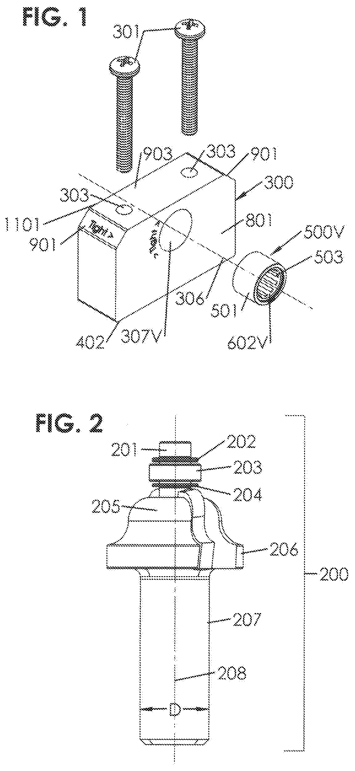
[0036]FIG. 1 is a partially exploded isometric view of a router bit vise according to an embodiment of the present invention. In this example a tool housing 300 includes an axial uniform diameter cylindrical through-bore 307V (hereafter named through-bore) having a centerline axis 306. The tool housing 300 is fabricated from a strong ...


PUM


Abstract

A router bit vise that holds and prevents the rotation of a router bit in a selected direction. It includes a tool housing and a cylindrical throughbore. Located in the throughbore is a one-way clutch assembly sized to accept a router bit shank. When inserted into the one-way clutch passageway, the router bit shank is engaged by the one-way clutch mechanism preventing movement in one rotational sense and allowing freewheeling movement in the opposite sense. No externally applied clamping force is required. With the router bit shank engaged with the one-way clutch circumferential rotation of the router bit is controlled allowing for bit maintenance, including cleaning, sharpening and most importantly enabling the application of the torque necessary to tighten or loosen a router bit fastener with no potential for shank slipping or damage.

Description

CROSS-REFERENCE TO RELATED APPLICATIONS[0001]The present application claims priority to provisional patent application number 62 / 754,025 filed on Nov. 1,2018, disclosures of which are incorporated herein at least by reference.BACKGROUND OF THE INVENTION1. Field of the Invention[0002]The present invention is in the field of router bits and pertains particularly to controlling the rotation of the router bit shank.2. Discussion of the State of the Art[0003]Routers are tools used for removing material from a workpiece. The workpiece material is usually wood or metal but can be other natural or synthetic substances. Powered routers include a spindle that can be electrically, pneumatically, hydraulically, or manually rotated to spin an interchangeable router bit cutter. The router bit cutter is securely attached to the router spindle with a nut and sleeve compression system, referred to as a collet.[0004]Router bit cutter constructions range from a single piece to those having multiple pa...

Claims


Application Information

Patent Timeline
IPC IPC(8): B23C5/24B27C5/10B23C5/10
CPCB23C5/24B23C5/10B27C5/10B23B31/223B23B2260/044B25B3/00B23Q3/00B25B1/08B25B1/20
Inventor MILLER, JAMES ROBERT
Owner MILLER JAMES ROBERT
Why Eureka
Try Eureka